Authors: Gopal Raghav1, Swaminathan Gopalswamy1, Karthikeyan Radhakrishnan1, Jérôme Hugues2, Julien Delange3 1: Emmeskay Inc, 47119 Five Mile Road Plymouth, MI, U.S.A. 2: Toulouse University/ISAE at 10 avenue Edouard Belin – BP 54032, 31055 Toulouse CEDEX 4, France 3: TELECOM ParisTech, 46 rue Barrault, 75634 Paris, France
Abstract:Embedded systems are becoming increasingly complex and widely distributed. Cost and quality requirements necessitate the reuse of functional software components across various deployment architectures. Allocating software components to hardware is a critical step. In this process, it is essential to reconcile the differences between hardware and application software architectures. This paper discusses an architecture-driven approach that involves model-based techniques to address these discrepancies and integrate hardware and software components. The system architecture serves as the foundation for generating distributed real-time components. This paper discusses a method for generating various embedded system architectures using the same functional architecture. The approach leverages the following technologies: Integrated Modeling Environment (IME), SAE AADL (Architecture Analysis and Design Language), and Ocarina. The method is illustrated using an electronic throttle control system as an example.
Keywords:AADL, architecture-driven, distributed embedded software
1. Introduction
Embedded systems in ground vehicles are becoming increasingly complex in terms of the functionalities they support. Safety and security are paramount. Innovative approaches are needed to develop such systems efficiently without compromising quality. Model-Based Development (MBD) techniques are an increasingly popular trend in the development of complex embedded systems. Essentially, MBD involves modeling the behavior of embedded systems to simulate their performance under different operating conditions and stimuli. MBD supported by CAE tools facilitates the design of advanced control functionalities through early verification and validation (V&V) before mechanical and electronic hardware is available. The state of MBD technology has evolved to the point where embedded software can be automatically generated from functional models. Such tools and processes help generate code for individual ECUs. However, in practice, two key demands arise as the number of processors and the complexity of algorithms increase:
(i) Development frameworks need to support modular development of embedded software to enhance reusability. Additionally, we need to support multiple variants of reusable component implementations. This leads to the idea of “architecture” as the foundational description of the system, with variant management built around that architecture—Architecture-Driven Development (ADD). These issues have been addressed in previous research (e.g., [1]).
(ii) The second demand relates to the fact that the functional model of the application often has an architecture that is distinctly different from the architecture of the application embedded software. The functional architecture of the system corresponds to the optimal architecture required for control system development and is related to the functional performance of the controlled physical system. On the other hand, the architecture required for any application’s embedded system is related to the number of processors, different tasks and threads, and their scheduling. We need a clear approach to address these discrepancies.
This paper focuses on the second demand mentioned above. Specifically, it explores an extension of existing techniques that allows for the generation of distributed embedded software from functional models, thereby seamlessly reconciling the differences between functional architecture and embedded system architecture.
In addition to the above considerations, a single functional architecture can often support multiple embedded system architectures. For example, the hardware used in the system may undergo technological advancements, necessitating a new hardware architecture even if the functional architecture remains unchanged. It is also common to reuse software components between different vehicles where the functional architecture may change but the hardware architecture remains constant. The method discussed in this paper also addresses other practical issues related to the development of complex large embedded systems. Section 2 discusses the architecture-driven development approach used to generate distributed software.
This section describes two main activities: (a) developing a functional model consistent with the system architecture; (b) generating distributed embedded software. It also discusses the workflow for executing these activities. Section 3 discusses the supporting tools and techniques used in this process. Our work utilizes three main technologies: SAE AADL (Architecture Analysis and Design Language), IME (Integrated Modeling Environment), and Ocarina (an AADL tool suite with code generation capabilities). Section 4 describes a case study using an electronic throttle control application. Finally, in Section 5, we summarize our findings.
2. Architecture-Driven Approach
The system architecture serves as the basis for generating functional models, embedded system models, and software. The approach primarily consists of two main activities. First, the system architecture needs to be defined, and a functional model (executable specification) consistent with the system architecture must be developed. Second, the functional model should be integrated with the hardware architecture and embedded software generated from a complete system model.
2.1 Generation of Functional Models
In our proposed method, the generation of functional models can be accomplished through four key steps:
(i) Definition of Functional Architecture:
The first step is to develop the system architecture. The architecture is the topology of the system, describing the structural hierarchy of subsystems and their interfaces and connections. This step involves multiple stakeholders—control engineers, software engineers, and management. Typically, this step is performed by the original equipment manufacturer (OEM) based on product goals and requirements. The architecture can then be used to communicate requirements to the suppliers of the various components in the system, which may be a department of the OEM or external suppliers.
(ii) Organizing and Mining Component Functional Model Libraries:
One step that occurs in parallel with the architecture is the development of component models. To maximize reuse, organizations gradually develop modular component models and collect them into a library accessible to all authorized developers. The larger the library of such models, the faster the development of functional applications. However, it is crucial to keep the library well-organized and easily searchable. In particular, the ability to search the library based on the architectural metadata of component models (e.g., their interfaces, hierarchy, etc.) will significantly enhance the efficiency of application development.
(iii) Associating Component Models with Architecture:
Since we want the application model to be consistent with the system architecture, we need to identify component models that conform to the company hierarchy. As part of this association, the ability to search architectural metadata in the model library should be utilized to verify the consistency of the architecture. Both structural and interface consistency must be ensured. Additionally, constraints specified in the architecture can be combined with the metadata of the component models being inserted to facilitate guided searches of the model library.
(iv) Generating Simulatable Application Models:
The final task is to generate simulatables application models to confirm the functionality of the control system. For example, we can start from the system architecture and build models in simulation domains such as Simulink [2]. Figure 1 shows some steps in the process of generating functional models.
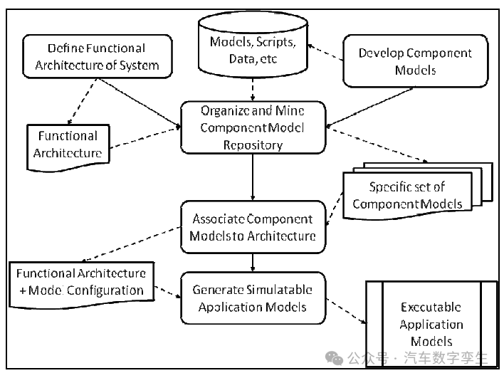
Figure 1: Steps in the process of generating (executable) application models from functional architecture
2.2 Generation of Distributed Embedded Software
The generation of distributed embedded software can be summarized in the following steps:
(i) Definition of Embedded System Architecture: The embedded system architecture involves the processors in the system, the information for communication between processors, the processes and threads within each processor, and the scheduling of these processes and threads. AADL is a powerful mechanism for describing and conveying such architectures [3]. Therefore, the embedded system architecture is developed collaboratively by stakeholders consisting of project managers and embedded software and hardware engineering teams.
(ii) Coordination of Functional Architecture with Embedded System Architecture: It is important to note that the architecture used to generate functional models is often distinctly different from the embedded system (hardware) architecture. The commonality between functional architecture and embedded system architecture is that they both have a set of associated component functional models. Therefore, to coordinate the functional architecture with the embedded system architecture, a key step is to define the binding between the component functional models in the functional architecture and the nodes in the embedded system architecture. Once such bindings are completed, it is essential to ensure that the functional connectivity between the software components specified in the functional architecture is not compromised while satisfying the communication requirements of the embedded system architecture.
(iii) Generation of Distributed Embedded Software: The final step in this process is to generate distributed embedded software based on the embedded system architecture and the associated component models.
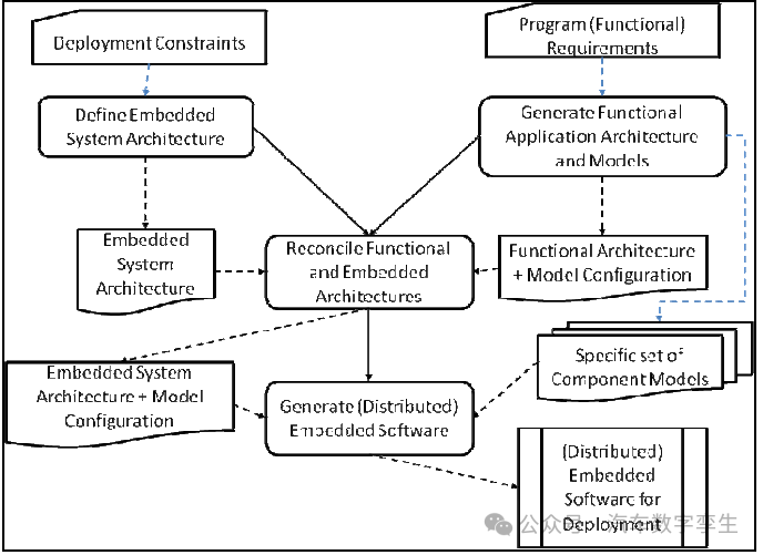
Figure 2: Steps in the process of generating (distributed) embedded software for deployment
This workflow is illustrated in Figure 2 above. If there exists an automated process for generating distributed embedded software from the architecture, it would provide a powerful method for generating different deployment variants of distributed embedded systems, all based on the same functional architecture. Different deployments may impose different constraints, which can be easily adapted through appropriate bindings between the embedded architecture and functional architecture. (See Figure 3 below)
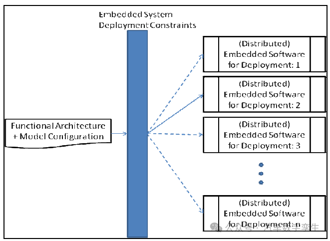
Figure 3: A single functional architecture can support multiple deployment architectures
Examples of multiple deployments for a given functional architecture are as follows: (i) A low-cost solution requires deploying the entire application on a single processor, accepting the associated schedulability issues and the resulting performance degradation. (ii) A medium-cost solution allows intelligent actuators and/or smart sensors to run part of the functionality on local processors, enabling faster internal feedback and thus improving system performance; most functionalities still run on a central processor. (iii) A high-cost system requires separate processors to provide monitoring, safety, and redundancy functionalities. By using the advocated method, each deployment can be conveniently initiated from a generic functional architecture.
3. Supporting Technologies
In the previous section, we discussed how the system architecture drives the various activities involved in the generation of embedded software. To effectively implement these processes, several supporting technologies are required:
Architecture Description Method: To coordinate functional architecture and hardware architecture, the primary requirement is that we need to be able to standardize the description of both architectures. This Architecture Description Language (ADL) needs to be capable of specifying multiple different components (functional, software, electronic, sensors, and actuators) and their communication. In addition to listing the architectural view of the system topology, it is also necessary to specify relevant non-functional properties (priority, CAN bus time slots, memory capacity, etc.) at different nodes of the architecture. A well-defined mechanism is also needed to bind functional components to embedded system components while preserving their respective characteristics.
We chose SAE AADL as the backbone modeling notation because it is rich enough to serve as a good language for architecture-driven embedded system development. Furthermore, AADL is a tool-neutral language, which facilitates the exchange of architectural descriptions between different tools.
Architecture-Driven Modeling: We need an environment where (i) the architecture can be understood, and (ii) architecture transformations (from functional architecture to embedded system architecture) can be implemented. Such an environment should be able to link and manage the relationship between the architecture and the functional models developed using advanced modeling tools like Simulink. This environment should also support the migration of functional models to embedded system models.
In this paper, we use the commercial tool IME (Integrated Modeling Environment) to evaluate and demonstrate the method.
Architecture-Driven Embedded Software Creation: We need to be able to integrate technologies for embedded software and distributed real-time software components corresponding to functional models.
For generating embedded software corresponding to functional models, many native modeling tools provide this functionality. In this paper, we use Simulink as the modeling tool.
To generate real-time executables for distributed processor systems, we use Ocarina to evaluate and demonstrate the method. The Ocarina tool suite supports the generation of real-time executable code from AADL models and appropriately integrates software automatically generated from functional models.
These technologies—AADL, IME, and Ocarina—help designers seamlessly transition from high-level modeling to code writing and will be detailed in the following sections.
3.1. AADL
The Architecture Analysis and Design Language (AADL) was adopted as an SAE (Society of Automotive Engineers) standard in 2004. AADL is a tool-neutral language that can be used to describe the runtime architecture of embedded systems. Using these descriptions, model-based analyses such as schedulability, safety, and security can be performed [4]. It can describe the architecture of hardware and software components and data, as well as their variations in implementation. AADL components are described as component types and implementations.
Component types define the interfaces of components. Component implementations inherit the properties of component types and describe subcomponents and their connections. A single component type definition can have different component implementations, leading to multiple different implementations of the same component. The following AADL components are used in our work.
• System – These components can be used to describe the system architecture. They can represent any software or hardware component, or a combination of both.
• Process – Process components are software abstractions responsible for scheduling and executing threads. They execute in the memory of the processor.
• Thread – Thread components are software abstractions responsible for scheduling and executing subprograms. The execution period and execution time of threads can be set as properties.
• Subprogram – Subprograms represent basic code snippets that process inputs to produce outputs. AADL only describes the interface. The implementation must be provided by the host language. In our work, the functional models developed using Simulink provide the implementation.
• Processor – These components are abstractions of the hardware and software that schedule and execute processes. Each processor has its own clock, which serves as the reference time for all components running on the processor.
• Bus – Bus components are used to exchange data between hardware components.
[5] provides a complete description of AADL. The AADL system components can be used to initially describe the functional architecture. Ports and connections define the component interfaces and communication. Once the functional model is associated with the system components, the architecture can be migrated to the behavioral modeling domain. The system components can then be transformed into embedded components consisting of processors, processes, threads, and subprograms.
3.2. Integrated Modeling Environment (IME)
IME is a model management and architecture creation and analysis tool [6]. As discussed in Section 2, the system architecture drives the creation of functional models and the generation of distributed software. A visual environment must be provided for the system architecture. This environment should be able to exchange architectural descriptions with other tools.
Over time, the developed component behavioral models are archived in a model repository for reuse. To find consistent models, their architectural information must be extracted and stored.
Intelligent queries for searching certified models and consistency checks help in model selection. Once the selection is complete, the architecture must be migrated to the behavioral modeling domain. As described in Section 2.2, functional models must be seamlessly integrated with the hardware architecture description. In this step, the environment must facilitate engineers in defining the bindings between functional components and embedded components. These bindings define the allocation of functional components to AADL processes that must be bound to AADL processors. AADL processor components represent different ECUs. Once the bindings are defined, the embedded system architecture must be generated. The AADL description must be exported from this architecture. IME is a tool that supports all of the above activities. The generated AADL models can be used for code generation.
3.3. Ocarina
Ocarina [7] is a tool suite developed by the AADL group at TELECOM ParisTech. It aims to provide AADL model manipulation, syntactic/semantic analysis, model analysis capabilities (using external tools such as Cheddar [8]), or embedded functionalities (e.g., generating Petri net models, analyzing models using REAL constraint language).
Additionally, Ocarina recommends using the PolyORB-HI series AADL runtime to convert AADL models into code in C or Ada languages. The runtime code and generated code strictly adhere to the requirements for high integrity domains in aerospace, avionics, or automotive fields.
The target RTOS ranges widely, including bare-metal Ada runtimes, real-time executables (such as RTEMS or RT Linux), domain-specific operating systems (such as POK for avionics systems), and native platforms for rapid prototyping. Ocarina supports both AADLv1.0 and AADLv2. Unlike many MDE tools, Ocarina relies on its own internal metamodel engine, which is closer to a compiler AST. This allows for extensive internal optimizations, enabling fast and efficient processing of large models.
Ocarina is licensed under the GPL and runs on most operating systems (Windows, Mac OS X, and Linux). Our AADL portal [10] provides versions, application-level model examples, case studies, and related documentation. Ocarina has been successfully tested in European projects led by the European Space Agency, IST ASSERT [11], and the French R&D project led by Thales, Flex-eWare [12]. As part of an advanced technology transfer project, their partners are currently further testing Ocarina based on industry-scale case studies.
A notable feature of Ocarina is its ability to seamlessly integrate any functional symbol as an implementation of a block (e.g., subprogram or thread). Designers do not need to write C code; they simply insert SCADE or Simulink functional blocks. The Ocarina code generator then generates all necessary glue code to integrate the C code generated by Simulink Real-Time Workshop or the kcg C code from SCADE into the AADL runtime code. This avoids tedious and error-prone integration work and allows users to focus on the behavior of the system without worrying about the underlying implementation details. This feature allows for a natural bridge between simulation on real hardware and high-level architecture-based tools (such as IME) using code generated by Ocarina in a distributed setting. We will illustrate this in the next section.
4. Case Study
In this section, we will describe the application of the architecture-driven approach in the electronic throttle control (ETC) system. ETC replaces the mechanical system consisting of a throttle pedal and a linkage between the pedal and the throttle plate. In the mechanical system, the vehicle driver adjusts the position of the throttle plate via the throttle pedal, directly regulating the airflow to the engine. At idle, airflow bypasses the throttle plate, regulated by the idle air control (IAC) valve. In the ETC system, the throttle plate is electronically driven. The desired position of the throttle plate (setpoint) depends on the pedal position and other inputs and operating conditions. The main advantage of ETC is that it allows system designers to integrate throttle control with other vehicle functions, such as cruise control and vehicle stability control. ETC is considered a safety-critical system. Therefore, a significant portion of the ETC functionality is dedicated to redundancy and safety monitoring. Figure 4 shows the functional architecture of an ETC system in IME. The main components of this architecture include the core controller, actuators, sensors, and the controlled object. The core controller contains three important functions: safety monitoring, management, and servo control.
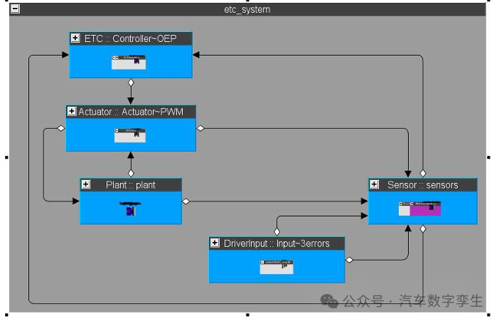
Figure 4: ETC Closed-Loop System
In this case study, we will consider three deployment scenarios for the embedded software.
Scenario 1 – Single ECU: We consider a situation where the supplier is responsible for developing the actuator system. The supplier develops the initial version of the actuator based on the OEM’s specifications. The product development cycle requires the entire system to be virtually integrated before the actual physical hardware is available. Therefore, the supplier develops actuator driver models and object models and delivers the closed-loop actuator system model to the OEM. The OEM integrates the actuator model into a larger ETC system model. The next step for the OEM is to deploy all controller components onto a single target ECU to ultimately generate the control software.
Scenario 2 – Single ECU + Smart Actuator: As an alternative to Scenario 1, the supplier provides a technologically advanced actuator where the driving software is tightly integrated with the physical actuator. This allows the OEM to offer superior functionality in part of its product line without affecting the underlying hardware architecture. However, in this case, the actuator driver software executes on a dedicated ECU. When the supplier delivers the actuator driver and object models to the OEM for integration into the ETC system model, the OEM must ensure that the code generation does not include the driver for the main ECU.
Scenario 3 – Dual ECU + Smart Actuator: The OEM wishes to reuse the same physical system and control architecture for advanced defense applications that place a high emphasis on safety-criticality and redundancy. To accommodate this modification, the OEM wants to deploy the safety monitoring component on a separate target ECU; core functionalities run on the main ECU; and the driver runs on the processor used with the actuator.
In all the above scenarios, the functional architecture remains unchanged, but the deployment architecture varies. We will now discuss the workflow and toolchain supporting the deployments of the above scenarios.
Figure 5 describes the steps involved in generating functional models from the system architecture.
AADL authoring tools (e.g., OSATE (Open Source AADL Tool Environment) [5]) can be used to develop the system architecture and import it into IME.
The model library can be mined, and consistent functional models can be selected and associated with the system architecture. The Simulink functional model of the system can then be generated for further analysis.
The next step is to deploy the functional model on the target. Since the functional architecture differs from the target architecture, and the target architecture also varies across the three scenarios, significant redesign of the functional architecture is required. The workflow for allocating functional software components to targets is shown in Figure 6.
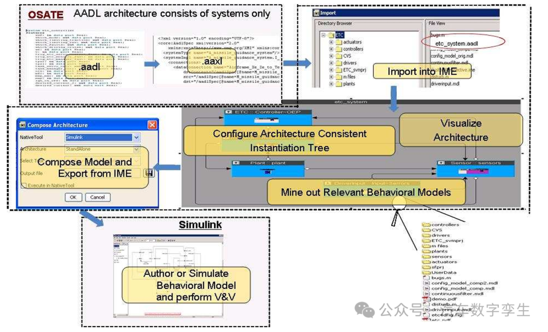
Figure 5: Generating functional models consistent with the system architecture.
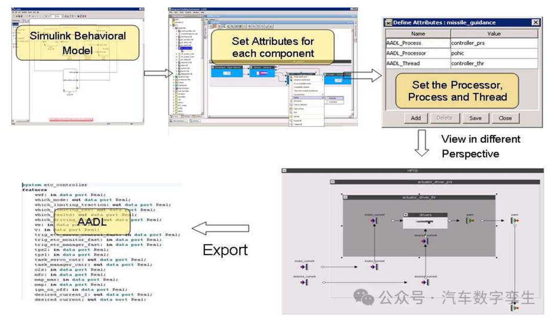
Figure 6: Generating embedded system architecture from functional architecture
The functional system architecture can be annotated with binding information. The binding information varies across the three deployment scenarios. The binding information must include the processor, process, and thread in which each component must execute. The embedded architecture is then generated from the functional architecture. Figures 7, 8, and 9 show the embedded architectures for scenarios 1, 2, and 3, respectively. Figure 9 shows the detailed hierarchy of the embedded system. The embedded system consists of two ECUs—ECU1 and ECU2. A process is executed in ECU1, managing a thread. This thread executes the monitoring component. The connections to the controlled object are not shown in the figure. In all three target architectures, the communication between software components is conducted as specified in the functional architecture.
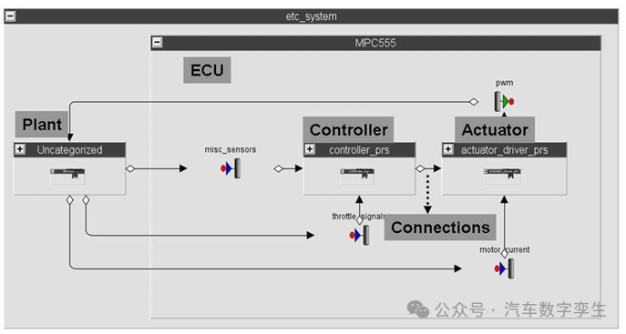
Figure 7: Scenario 1 – Controller and actuator driver executing in a single ECU
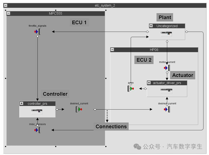
Figure 8: Scenario 2 – Actuator driver executing on a dedicated ECU
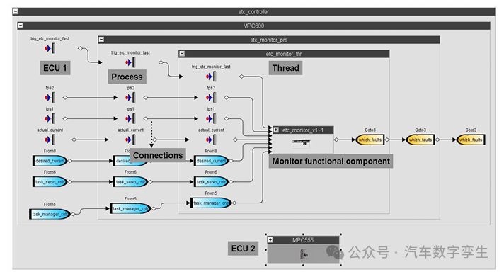
Figure 9: Scenario 3 – Monitoring component executing in a dedicated ECU. Other controller components executing in another ECU.
The next step is to generate embedded software. In scenarios 1 and 2, the controller components are deployed on a single ECU. Therefore, the restructured embedded architecture can be migrated back to the Simulink domain, which supports code generation for a single ECU. In scenario 3, the controller components are distributed across two ECUs. To generate distributed software from a single model, the architecture is exported as an AADL model. The Ocarina tool suite can parse the AADL model and extract the execution characteristics of the embedded system. Executables can be generated for each process. Within each process, the required threads are created, which in turn call subprograms representing the functional component interfaces. At the same time, code can be generated based on the functional model of each component. These functional components are called within the subprograms. Figure 10 shows the execution architecture and the communication between embedded components and functional components. Figure 11 illustrates the structure of the monitoring subprogram and the calls to the monitoring functional component. The integrated software can be executed on real-time systems.
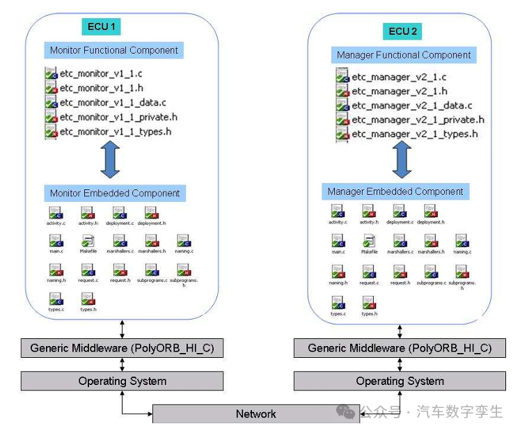
Figure 10: Communication between monitoring component and manager component executing in a standalone ECU.
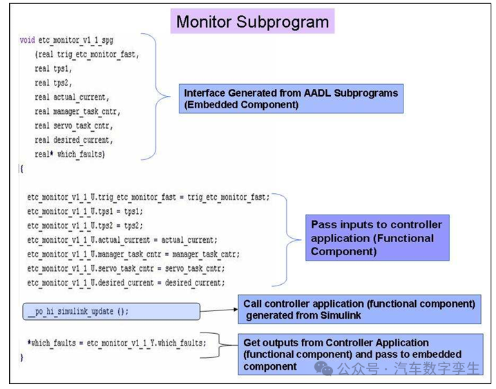
Figure 11: Structure of the subprogram
5. Conclusion
In this paper, we discussed methods and specific techniques for generating distributed embedded software from functional models. The architecture-driven approach helps reconcile functional architecture and embedded architecture and achieve integration. Specific tools and techniques also support modular development and reuse of software components. These improvements enhance the efficiency of engineering activities. Further research is needed regarding the deployment of embedded software on target hardware and system real-time testing.
6. REFERENCES
[1] S. Gopalswamy, et.al., “Practical Considerations for the Implementation of Model Based Control System Development Processes”, Proceedings of the Conference on Control Applications, 2004.
[2] Simulink is a registered trademark of The Mathworks, www.mathworks.com .
[3] SAE. Architecture Analysis & Design Language v2.0 (AS5506), September 2008.
[4] B. Lewis, P. Feiler, Multi-Dimensional Model Based Engineering for Performance Critical Computer Systems using the AADL, ERTS 2006, Toulouse, France.
[5] The SAE AADL, www.aadl.info .
[6] IME, http://www.emmeskay.com/tools/ime .
[7] “OCARINA: An Environment for AADL Models Analysis and Automatic Code Generation for High Integrity Applications” Gilles Lasnier, Bechir Zalila, Laurent Pautet, and Jérôme Hugues. Reliable Software Technologies’09 – Ada Europe. Brest, France. June 2009 pp. 237-250
[8] Cheddar, http://beru.univ brest.fr/~singhoff/cheddar
[9] J. Delange, L. Pautet and F. Kordon. Code Generation Strategies for Partitioned Systems. In 29th IEEE Real-Time Systems Symposium (RTSS’08) Work In Progress, IEEE Computer Society, December 2008.
[10] http://aadl.telecom-paristech.fr .
[11] http://www.assert-project.net
[12] http://www.flex-eware.org