1. Introduction
We have completed the foundational work, enabling us to have shell interaction capabilities, allowing arbitrary import and export of content in on-chip memory and SPIFLASH. Now we can enter the most critical phase: programming the image and loading it to run. First, we need to design the storage structure of the image in SPIFLASH. We need a HEAD information structure to inform the boot where the device tree is, where the kernel image is, and where to load the device tree and kernel, among other details. Then we need to implement the loader LOAD functionality to load the device tree and kernel from SPIFLASH into SDRAM for execution. This article will cover this part.
Code can be found at: https://github.com/qinyunti/stm32f429-boot.git
2. Storage Layout Design
Our primary task is to design the layout of the device tree and kernel image in SPIFLASH. Of course, there may also be other user-defined content in the layout of SPIFLASH, which can be managed through the HEAD information. This way, we only need to parse the HEAD to autonomously interpret the aforementioned information, allowing us to load specified content from designated addresses into SDRAM at specified locations.
The HEAD information is placed at a fixed address, here fixed at 0, and can also be fixed at other addresses. Thus, finding the HEAD allows us to parse other content addresses based on the HEAD.
We design the HEAD information and storage layout as follows:
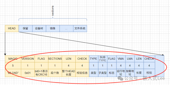
First, the entire storage is divided into two parts: HEAD and sections.
Among them, the HEAD information is fixed, while the sections can be allocated by the user. The device tree file and kernel image are mandatory, while others can be allocated to the root filesystem, reserved area, user filesystem, etc.
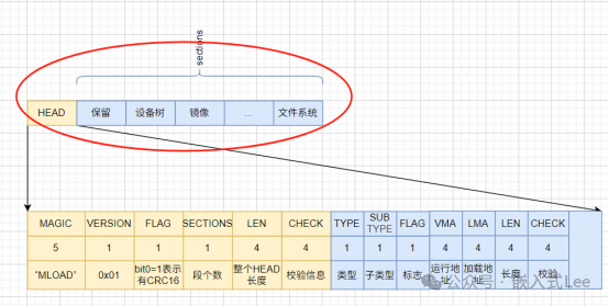
The HEAD is defined as follows, divided into header and section information parts.
The header structure is as follows. Note that this structure does not require a binary correspondence with storage, so packed is not used. The structure and storage are manually converted without using forced type conversion to avoid alignment issues across different platforms, and load_section_info_ is the same.
/** * \struct load_head_st * HEAD information Here we do not use packed mode, HEAD structure and Buffer should preferably use manual conversion, do not use direct type casting */typedef struct{ uint8_t magic[5]; /**< "MLOAD" */ uint8_t version; /**< Version information */ uint8_t flag; /**< Flag indicating whether HEAD has checksum information */ uint8_t sectinos; /**< Number of subsequent section_info */ uint32_t len; /**< Length of HEAD, including the entire area */ uint32_t check; /**< Checksum information for HEAD, if flag's bit0 is 1 */ /* The following are sectinos load_section_info_st */ load_section_info_st section_info[0];}load_head_st;Next, we have the information for each section, with the number of sections specified by sectinos in the header.
/** * \struct load_section_info_st * SECTION information */typedef struct{ load_section_type_e type; /**< \ref load_section_type_e */ uint8_t subtype; /**< Further distinction for user-defined sections */ uint8_t flag; /**< Flag indicating whether there is a checksum, encryption, etc. One type corresponds to one bit \ref load_section_flag_e */ uint32_t vma; /**< Destination address for loading, running address, i.e., address in SDRAM */ uint32_t lma; /**< Source address for loading, loading address, i.e., address in storage */ uint32_t len; /**< Effective data length of the section, in bytes */ uint32_t check; /**< Checksum for the effective data of the section */} load_section_info_st; Below we introduce the meaning of each field.
All fields use little-endian format.
Magic: Fixed as a 5-byte character “MLOAD“, which is the name of our loader, my load, MLOAD.
VERSION: Currently set to 0x01 version
FLAG: Indicates whether there is a checksum, currently bit0=1 indicates there is a CRC16 checksum, other bits are reserved for extension.
SECTIONS: Indicates the number of subsequent section information
LEN: Indicates the total length of the HEAD, which is 16+sections*19
CHECK: Indicates the checksum for the subsequent sections*18 bytes of section information. For FLAG‘s bit1=1, CRC32 is used.
Then we have the information for sections of sections.
TYPE indicates the type of section.
Currently, the following types are defined:
/** * \enum load_section_type_e * SECTION types */typedef enum{ LOAD_SECTION_TYPE_DTB, /**< Device tree section */ LOAD_SECTION_TYPE_KERNEL, /**< Kernel image section */ LOAD_SECTION_TYPE_ROOTFS, /**< Root filesystem section */ LOAD_SECTION_TYPE_USER, /**< Reserved section, can include multiple sections, user section can distinguish itself */ LOAD_SECTION_TYPE_RVD, /**< Reserved section */} load_section_type_e;SUBTYPE indicates when it is a USER section, used to distinguish different USER sections.
FLAG indicates flag information for whether there is a checksum, encryption, etc. Currently, bit1=1 indicates the use of CRC32
Bit4=1 indicates that loading is required.
/** * \enum load_section_flag_e * SECTION flag types */typedef enum{ LOAD_SECTION_FLAG_NONE = 0, /**< No flags */ LOAD_SECTION_FLAG_CRC16 = 1, /**< CRC16 checksum */ LOAD_SECTION_FLAG_CRC32 = 2, /**< CRC32 checksum */ LOAD_SECTION_FLAG_NEEDLOAD = (1u<<4), /**< Indicates whether loading is needed */} load_section_flag_e;VMA is the running address loaded into SDRAM
LMA is the offset address in storage, i.e., the loading address.
LEN is the effective length of the section in bytes.
3. Loader Design
3.1 Programming Section Functionality
We have previously established the capability to program any content to any address in FLASH. Therefore, we only need to prepare the HEAD and section content on the PC, and then write it using xmodem.
We can also add more shell commands, such as modifying head information, etc., which will be improved later. To facilitate this, we can design a host-side image packaging tool, which concatenates all sections and HEAD according to the layout into a single image, allowing for a single programming operation to SPIFLASH.
3.2 Loading Section Functionality
For details, see load.h/load.c, the design considers the need to adapt to different storage, so the underlying storage read and write interfaces are dynamically configured.
typedef uint32_t (*load_mem_write_pf)(uint8_t* buffer, uint32_t addr, uint32_t len);typedef uint32_t (*load_mem_read_pf)(uint8_t* buffer, uint32_t addr, uint32_t len); /** * \fn load_mem_itf_set * Set the storage read and write interface for LOAD * \param[in] write_itf Write interface * \param[in] read_itf Read interface */void load_mem_itf_set(load_mem_write_pf write_itf, load_mem_write_pf read_itf); void load_mem_itf_set(load_mem_write_pf write_itf, load_mem_write_pf read_itf){ s_load_mem_write = write_itf; s_load_mem_read = read_itf;} Initialization requires configuration.
/* SPIFLASH boot */ load_mem_itf_set(flash_itf_write,flash_itf_read); load_load_sections(); load_boot(); /* At this point, if there is a valid dtb and kernel loaded, it will start directly */ /* @todo Other boot */ //load_mem_itf_set(xxx_write,xxx_read); //load_load_sections(); //load_boot(); Then call
load_load_sections();
to load sections. This function parses the HEAD, then iterates through the sections to load each section.
int load_load_sections(void){ load_head_st hdr; load_section_info_st info; if((s_load_mem_write == 0) || (s_load_mem_read == 0)){ return -1; } /* First read the hdr part */ if(LOAD_HDR_LEN != s_load_mem_read(s_load_mem_buffer,LOAD_MEM_ADDR,LOAD_HDR_LEN)){ return -2; } /* Parse the hdr part */ hdr.len = 0; load_buffer2hdr(s_load_mem_buffer, &hdr); /* hdr part cannot exceed maximum value */ if(hdr.len > LOAD_HDR_INFO_MAX_LEN){ return -3; } if((hdr.magic[0] != load_mem_magic[0]) || (hdr.magic[1] != load_mem_magic[1]) || (hdr.magic[2] != load_mem_magic[2]) || (hdr.magic[3] != load_mem_magic[3]) || (hdr.magic[4] != load_mem_magic[4])){ return -4; } /* Read the info part */ if((hdr.len-LOAD_HDR_LEN) != s_load_mem_read(s_load_mem_buffer+LOAD_HDR_LEN,LOAD_MEM_ADDR+LOAD_HDR_LEN,hdr.len-LOAD_HDR_LEN)){ return -5; } /* Iterate through sections */ uint8_t* p_info = s_load_mem_buffer + LOAD_HDR_LEN; for(int i=0; i<hdr.sectinos; i++){ load_buffer2sectioninfo(p_info, &info); load_one_section(&info); } return 0;}Loading a single section means loading data from storage to the specified running address, only sections that need to be loaded will be loaded.
int load_one_section(load_section_info_st* section_info){ uint8_t* p_dst; if(section_info->flag & LOAD_SECTION_FLAG_NEEDLOAD){ /* Load */ p_dst = (uint8_t*)(section_info->vma); if(section_info->len != s_load_mem_read(p_dst, section_info->lma, section_info->len)){ return -1; } /* Checksum */ if(section_info->flag & LOAD_SECTION_FLAG_CRC32){ /* @todo */ } if(section_info->type == LOAD_SECTION_TYPE_KERNEL){ s_kernel_addr = section_info->vma; s_get_dtb_kernel_flag |= 0x01; }else if(section_info->type == LOAD_SECTION_TYPE_DTB){ s_dtb_addr = section_info->vma; s_get_dtb_kernel_flag |= 0x02; } } return 0;} 3.3. Boot Execution
The loading process above will record the addresses of the dtb and kernel.
Therefore, when calling load_boot, it will jump to the corresponding address to execute.
void load_boot(void){ if(s_get_dtb_kernel_flag == 0x03){ start_kernel(s_dtb_addr, s_kernel_addr); }}If the system loading from external storage fails, it will run from the default on-chip FLASH, ensuring safety.
This means that the on-chip FLASH retains a minimal version of the system, which is not modified after release, capable of running basic functions to enable communication and upgrade the system on external storage.
During normal operation, the system from external storage runs, and if there is an issue with the external storage system, the on-chip system will run, ensuring that the external system can still be upgraded.
/* SPIFLASH boot */ load_mem_itf_set(flash_itf_write,flash_itf_read); load_load_sections(); load_boot(); /* At this point, if there is a valid dtb and kernel loaded, it will start directly */ /* @todo Other boot */ //load_mem_itf_set(xxx_write,xxx_read); //load_load_sections(); //load_boot(); /* If there is no dtb and kernel loaded, start from the default address */ start_kernel(DTB_ADDR, KERNEL_ADDR);4. Conclusion
In this article, we have implemented the functionality of the load loader, which can parse the HEAD from storage and load the image for execution. In the next article, we will conduct a practical demonstration.