Produced by 21ic Forum Xiao Ye San Qian
Website: bbs.21ic.com
We usually use adjustable power supplies, which typically display two values: the current voltage set and the current flowing through the device. Below, I will introduce how to make a meter that can display both voltage and current values using the INA226 power chip.
1. Required Hardware
1. INA226 power chip; this is the main device for data acquisition, which will be introduced later.
2. Screen (using OLED12864-7 line SPI), for displaying voltage and current values.
3. Microcontroller (using New Tang N76E003); since we need to convert the acquired data into the values we want to display on the screen, a powerful MCU is not necessary; a basic 51 series MCU is sufficient.
4. Sampling resistor – 100mΩ. The INA226 requires a sampling resistor to obtain the current value, so it is best to choose a resistor with higher precision and greater power.
5. The rest are basic peripherals for the microcontroller, such as capacitors and resistors, which I won’t elaborate on.
2. Introduction to INA226
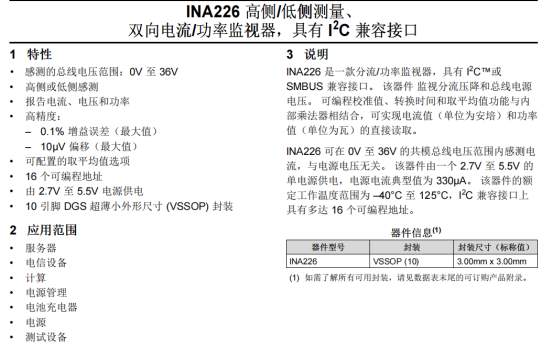
Just posting a screenshot; for more detailed content, refer to the chip manual in the attachment.
3. Hardware PCB
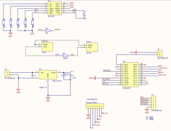
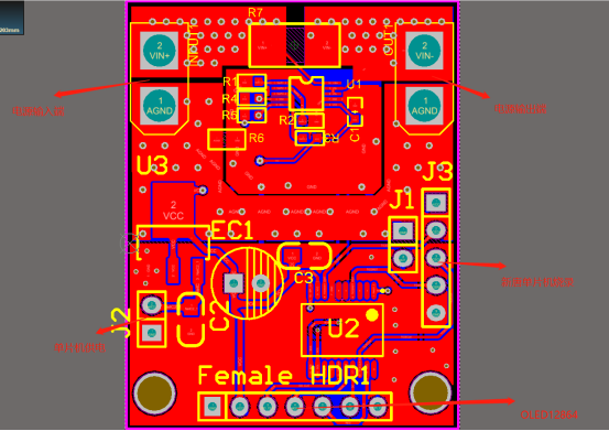
Based on the INA226 manual, I simply drew a PCB, integrating the microcontroller and OLED screen into the PCB. Please see the attachment for AD engineering.
Schematic:
PCB Diagram:
4. Software Development
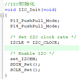
1. INA226 driver, IIC communication; I need to write the IIC driver in the microcontroller, details can be found in the attached IIC_INA226.c
2. Read and write operations for INA226
INA226 has 10 registers, of which 4 are read/write, and 6 can only be read.
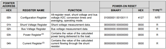
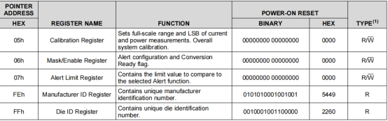
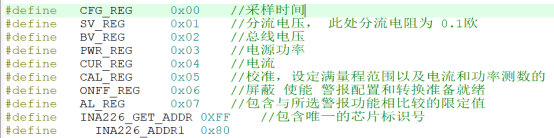
The meaning of each register is shown below, and it is also in the program.
Next is reading and writing registers for INA226
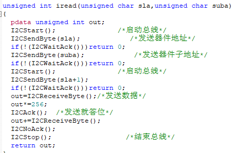
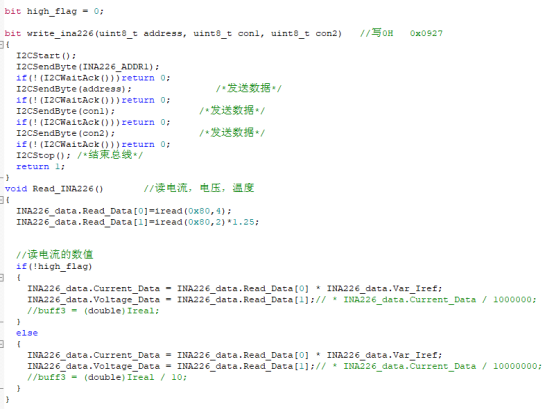
INA226_data.Read_Data[1] is the input voltage value, which is iread(0x80,2), reading from address 0x80 (the local address), where 0x02 is the register being read; according to the manual, 0x02 represents the bus voltage. If it is inaccurate, you can adjust the coefficient to 1.25. I feel it is quite accurate here.
INA226_data.Read_Data[0] is the input current value, which is iread(0x80,4), where 0x04 is the register being read; according to the manual, 0x04 represents the current, and INA226_data.Var_Iref is the coefficient used for calibration.
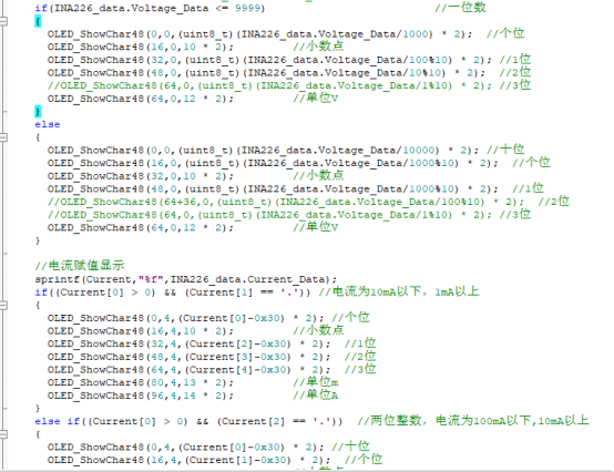
3. OK, the main part is done; next is the OLED12864 driver. I used large font display since the screen is small, so the text should be larger.
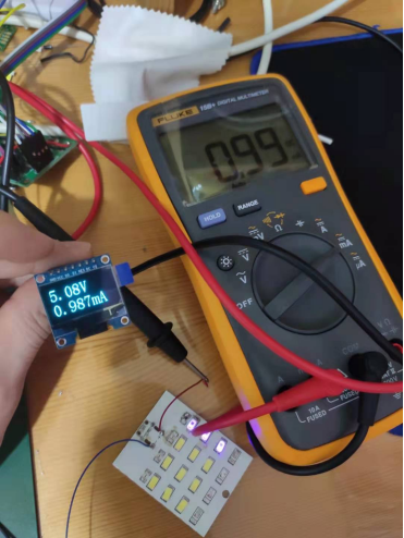
The image below shows the current and voltage values displayed.
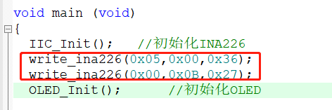
4. Almost finished; another important note is that during initialization, INA226 needs to write the sampling time and the current calibration value.
Register 0x05, the calibration register, how was 0x0036 calculated? The formula is in the manual.
Formula: 0.00512 / (Current resolution 0.001A * Sampling resistor 0.1) = 51.2 = 0x0033
After feeling it was not very accurate, I adjusted the value to 0x0036.
Register 0x00, the sampling time register. Set conversion time to 204us, average count to 128, sampling time is 204*128, and set mode to shunt and bus continuous mode.
5. Physical Debugging
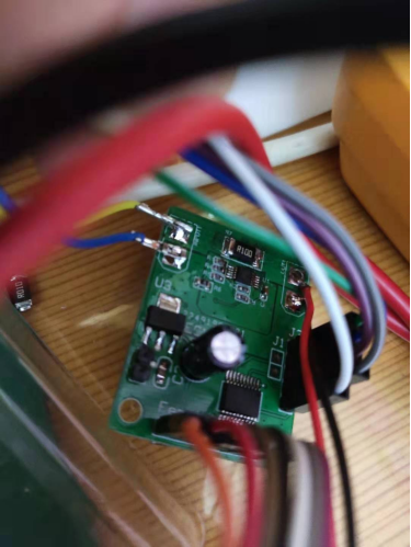
Next, I will burn the program into the microcontroller for debugging. The image below shows the completed physical device; it looks a bit low-end, haha. I debugged for a long time and changed a lot of hardware. The above are my experiences and insights, shared with everyone.
This article is originally by 21ic Forum user Xiao Ye San Qian. For data downloads, please click “Read Original”.Copyright belongs to the original author. If there is any infringement, please contact for removal.