People often ask, “What is your detection accuracy?”.
As the “skeleton” of electronic products, PCBs are essential in almost all electronic devices, from mobile phones to cars and servers. Nowadays, PCBs are evolving towards high density and multilayer designs, and relying solely on manual inspection cannot keep up with production capacity. Machine vision has become the “main force” in quality control. The accuracy of detection and the appropriateness of the light source are key factors—using a different light source with the same equipment can change the outcome from “missed detection” to “full inspection”.
Today, we will break down the five core scenarios of PCB inspection and explain which light sources to use for different situations, making the principles clear.
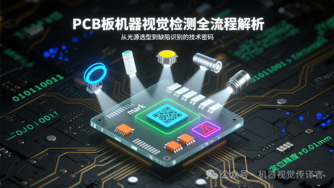
1. 🎯 Let’s start with a simple question: What are the challenges in PCB inspection?
There are many types of PCBs (single-sided, double-sided, multilayer, as well as flexible and rigid boards), and the “targets” for inspection are diverse: from millimeter-level mark points to micrometer-level scratches; from QR codes printed on the surface to components hidden under glue. The materials and reflective properties of these targets vary greatly, and to enable machines to “see clearly,” dedicated light sources must be matched to different “targets”.
2. 🎯 Five Inspection Scenarios + Light Source Selection, Just Follow This Guide
2-1. 🎯 Mark Point Positioning: Use Ring Light to Make the Positioning Point Stand Out
The mark points on a PCB are the “positioning anchors” for automated production, usually solid circles of solder. They need to be easily identifiable in images.ChoosingRing Lightis the most suitable: The ring light source illuminates from all around, causing the metallic surface of the mark point to reflect strongly, appearing particularly bright, while the surrounding substrate reflects weakly and has low brightness. This contrast creates a clear edge for the positioning point, allowing the system to quickly lock onto the center position with an error margin controlled within ±0.01mm.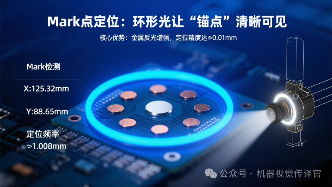
2-2. 🎯 QR Code Recognition: Coaxial Light Makes the Code Completely Black
QR codes on PCBs are often printed on smooth substrates, and if the angle of the light is incorrect, the reflection from the substrate can obscure the code.Coaxial Lightis the perfect match: It illuminates vertically from directly in front of the lens, and the light reflects back along the lens axis. The ink of the QR code absorbs light, appearing black; while the smooth surface of the substrate reflects light back to the lens, appearing bright. This high contrast of “black code on a bright background” can increase the decoding success rate from 80% to over 99%.
2-3. 🎯 Component Presence Detection: Dome + Coaxial Light to Handle Glue Reflection
When checking for missing components, the biggest issue is that the glue on the components can reflect light, making it easy for the system to misjudge whether a component is present or not.UsingDome Light + Coaxial Light Combination: Coaxial light illuminates vertically to reduce mirror-like reflections from the glue; dome light provides supplementary lighting from all directions, allowing for even diffuse reflection and avoiding overly bright “light spots”. The combination of these two types of light makes the surface of the glue appear soft, clearly revealing the contours of the components, reducing the missed detection rate to below 0.1%.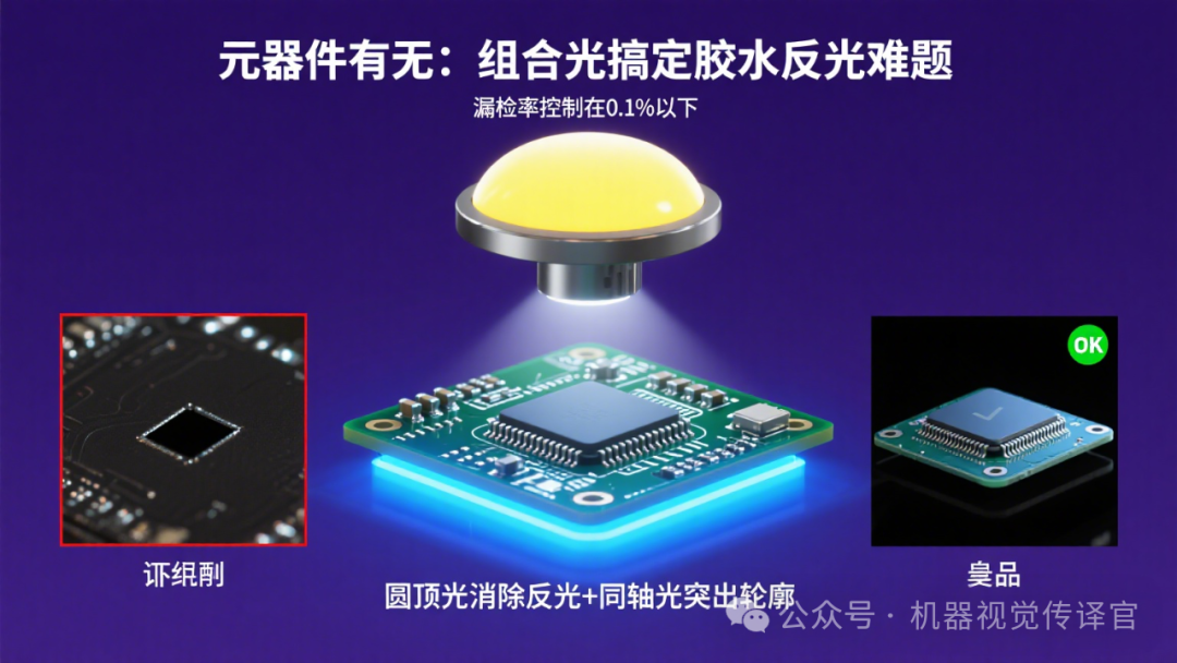
2-4. 🎯 Character Recognition: Tunnel Light Makes Small Characters Clear
The model and parameter characters on PCBs are mostly silk-screened, with some characters smaller than sesame seeds, and strokes as fine as 0.1mm. Uneven lighting can cause “broken strokes”.Tunnel Lightis the best choice: It illuminates from both sides and the top simultaneously, allowing the light to fill the entire character area. The character surface reflects light evenly, while the background substrate reflects weakly, capturing every detail of the strokes. Even blurred or incomplete characters can be recognized and completed by the system through algorithms.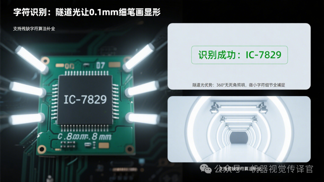
2-5. 🎯 Defect Detection: Coaxial Light “Magnifies” Scratches and Impurities
Small defects on the surface of PCBs, such as scratches, holes, and solder dross, are difficult to detect with the naked eye but can affect circuit performance.High Brightness Coaxial Lightcan make defects “visible”: The normal surface of the substrate reflects light evenly, appearing bright; while scratches scatter light and holes absorb light, making these defects appear as dark spots or lines in the image, contrasting sharply with the surrounding bright areas. Even small scratches of 0.05mm cannot escape detection.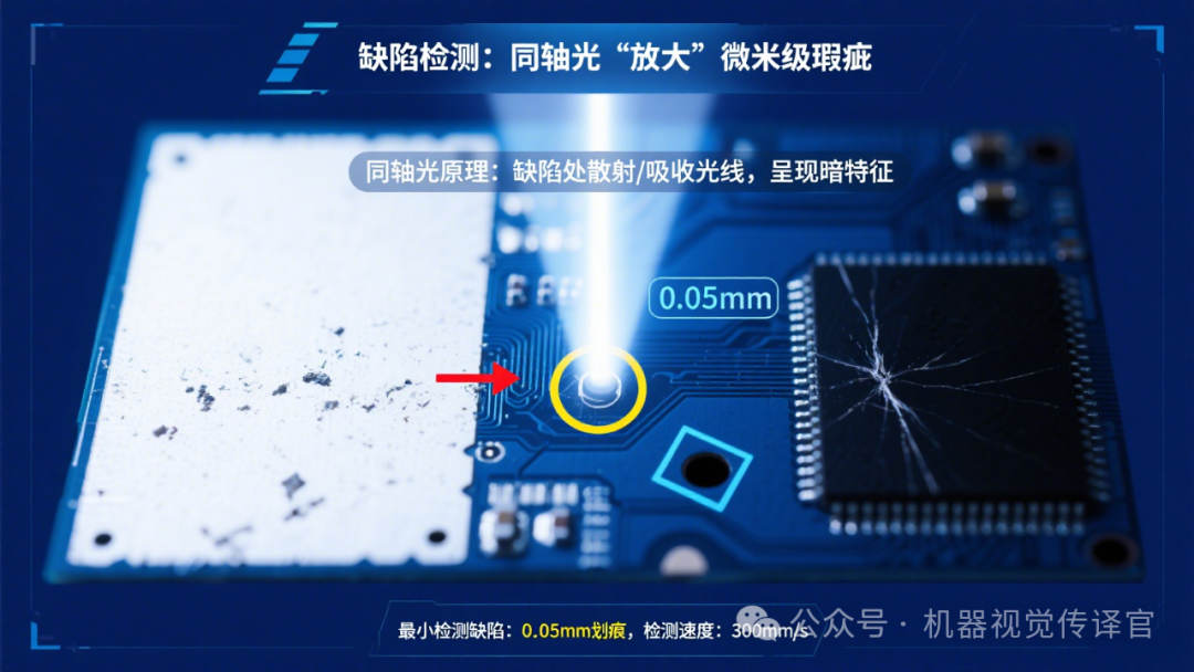
🎯 Conclusion: Choosing the Right Light Source Doubles Inspection Efficiency
Machine vision provides “health checks” for PCBs, and the core issue is not how expensive the equipment is, but whether the light source can “target the symptoms”—mark points need to be bright, QR codes need to be black, characters need to be clear, and defects need to be visible. Choosing the right light source can not only improve detection accuracy by an order of magnitude (from 0.1mm to 0.01mm) but also stabilize the system and reduce misjudgments by 90%.As PCBs become increasingly precise, the “customization” of light sources will become more important. After all, enabling machines to “see clearly” is the first step in all inspections.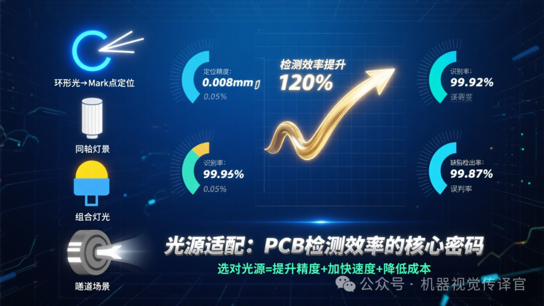
The images used above are sourced from the internet. If there are any copyright issues, please contact the author within 24 hours for resolution.
The End