1、 NMT Messages
1.1、NMT Module Control
Only the NMT-Master node can send NMT ModuleControl messages. All slave devices must support NMT module control services. The NMT Module Control message does not require a response. The NMT message format is as follows:
NMT-Master → NMT Slave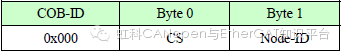
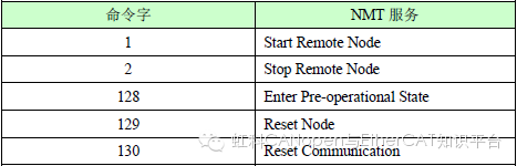
When Node-ID=0, all NMT slave devices are addressed. CS is the command word, which can take the following values:
1.2、NMT Node Guarding
Through the node guarding service, the MNT master node can check the current status of each node, which is particularly meaningful when these nodes are not transmitting data.
The NMT-Master node sends a remote frame (no data) as follows:
NMT-Master → NMT Slave
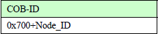
The NMT-Slave node responds with the following message:
NMT Slave → NMT-Master
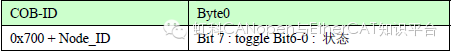
The data part includes a toggle bit (bit7), which must alternate between “0” and “1” in each node guarding response. The toggle bit is set to “0” during the first node guarding request. Bits 0 to 6 (bits0~6) represent the node status and can take values from the table below.
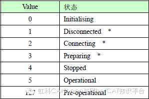
Note: States marked with * are only provided by nodes that support extended boot-up. Note that state 0 never appears in the node guarding response, as a node in this state does not respond to the node guarding message.
Alternatively, a node can be configured to generate periodic messages called heartbeat messages (Heartbeat).
HeartbeatProducer → Consumer(s)

The status can take values from the table below:
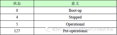
When a Heartbeat node starts, its Boot-up message is its first Heartbeat message. The Heartbeat consumer is usually the NMT-Master node, which sets a timeout value for each Heartbeat node, taking appropriate action when a timeout occurs.
A node cannot support both Node Guarding and Heartbeat protocols simultaneously.
1.3、NMT Boot-up
The NMT-slave node publishes a Boot-up message to notify the NMT-Master node that it has transitioned from the initialising state to the pre-operational state.
NMT Slave → NMT-Master

2、Process Data Objects (PDO)
As an example, assume the second transmit-PDO is mapped as follows (described in the CANopen object dictionary with index 0x1A01):
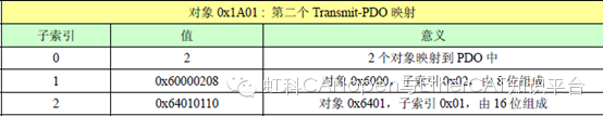
In the CANopen I/O module’s device profile (CiA DSP-401), object 0x6000 sub-index 2 is the second group of 8-bit digital inputs for the node, while object 0x6401 sub-index 0x01 is the first group of 16-bit analog inputs for the node.
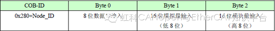
This PDO message, if sent (possibly triggered by input changes, timer interrupts, or remote request frames, consistent with the PDO transmission type, can be found in object 0x1801 sub-index 2), consists of 3 bytes of data, formatted as follows:
PDO-producer → PDO-consumer(s)
The content of the PDO can be changed by altering the content of object 0x1A01 (if the node supports (variable PDO mapping)).
Note that in CANopen multi-byte parameters are always sent in LSB (little endian).
It is not permitted to map more than 8 bytes of data to a single PDO.
The CANopen Application Layer and Communication Profile (CiA DS 301 V 4.02 ) defines MPDO (multiplexor PDO), allowing a single PDO to transmit a large number of variables by including source or destination node ID, index and sub-index in the message data bytes. For example: without this mechanism, if a node has 64 16-bit analog channels, it would require 16 different Transmit-PDOs to transmit data.
3、Service Data Objects (SDO)
SDO is used to access an object’s dictionary of a device. The accessors are called clients, while the CANopen devices being accessed and providing the requested services are called servers.
The client’s CAN messages and the server’s response CAN messages always contain 8 bytes of data (although not all data bytes necessarily have significance). A client’s request must have a corresponding response from the server.
SDO has two transfer mechanisms:
◆Expedited transfer: up to 4 bytes of data
◆Segmented transfer: for data lengths greater than 4 bytes
The basic structure of SDO is as follows:
Client → Server / Server → Client
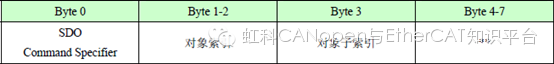
(**Maximum 4 bytes of data (expedited transfer) or 4 bytes byte counter (segmented transfer) or about block transfer parameters)
Or
Client → Server / Server → Client

SDO command words contain the following information:
◆Download / Upload
◆Request / Response
◆Segmented / Expedited transfer
◆CAN frame data byte length
◆Toggle bit for alternating zeroing and setting for each subsequent segment
SDO implements five request / response protocols: Initiate Domain Download, Download Domain Segment, Initiate Domain Upload, Upload Domain Segment, and Abort Domain Transfer.
In the latest version of the CANopen communication protocol, a new SDO transfer mechanism has been introduced:
Block transfer: when the data length exceeds 4 bytes, multiple segments are acknowledged by only one confirmation message response (if downloading, initiated by the server; if uploading, initiated by the client) to increase bus throughput.
The corresponding protocols are: Initiate Block Download, Download Block Segment, End Block Download, Initiate Block Upload, Upload Block Segment, and End Block Upload.
Download refers to write operations to the object dictionary, while Upload refers to read operations from the object dictionary.
Below are several examples illustrating how to use SDO to access an object’s dictionary of a node.
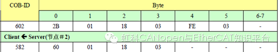
Using the following SDO message, the value 0x3FE will be written to the object dictionary of the node with ID 2 at index 0x1801, sub-index 3, using the Initiate Domain Download protocol with expedited transfer (2 bytes of data)
Client → Server (Node #2)
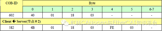
Using the following SDO message, the same object dictionary at index 0x1801, sub-index 3 will be read, using the Initiate Domain Upload protocol, with the server responding using expedited transfer (2 bytes of data):
Client → Server (Node #2)
4、Emergency Object(EmergencyObject)
Emergency indication messages are triggered by fatal errors occurring within the device and are sent by the relevant application device at the highest priority to other devices. This is suitable for interrupt-type error alarm signals.
An emergency message consists of 8 bytes, formatted as follows:
sender → receiver(s)
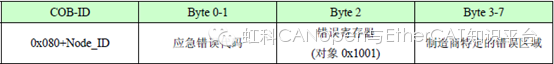
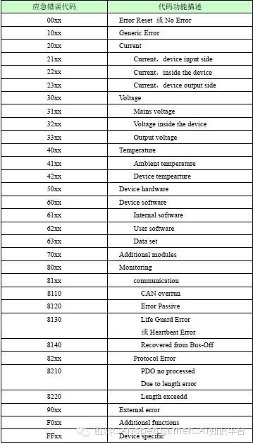
Hexadecimal emergency error codes are shown in the table below:
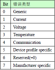
Error Register(Error Register) in the device’s object dictionary (index 0x1001) is defined in table 3-6. The device can map internal errors to this status byte and quickly view the current error.
The manufacturer-specific error area may contain additional error information related to the device.