 Low Power Design Methods – Frequency and Voltage Scaling
The practical operational space of circuit design lies in the process, design goals, process libraries, and timing analysis methods. Under special processes, temperature inversion particularly limits the range of timing, voltage, and temperature to maintain their normal monotonic relationship. A detailed analysis of all these factors is required before starting DVFS design.
-
Dynamic Power and Energy Consumption
The dynamic power consumed by CMOS is primarily described by the following equation:

Since dynamic power is linearly proportional to the switching frequency, dynamically reducing the switching frequency when maximum performance is not required can reduce dynamic power.
Dynamic power is also linearly proportional to the switching capacitance. Reducing capacitance is more of a design and implementation constraint, primarily improved by reducing the length of interconnect drives and simplifying design complexity to reduce area.
The voltage term has the greatest impact on power consumption; when frequency can be reduced to allow voltage reduction, power consumption decreases quadratically.
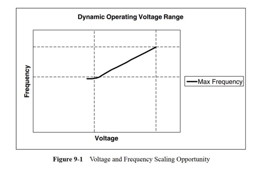
The figure below shows a working area where frequency monotonically increases with voltage, specifying the maximum and minimum voltages that can be operated under this process. It is important to note that operating outside the specified voltage range may lead to non-linear changes in delay and deteriorate circuit reliability.
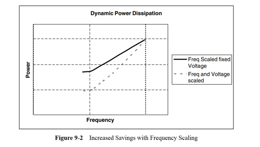
The figure below illustrates the power consumption when reducing frequency and voltage versus reducing frequency without lowering voltage. The gap between the two curves represents the achievable power savings between the minimum and maximum operating voltages.
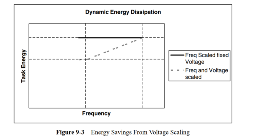
Energy consumption is the product of the power consumed during the time required to complete a task. Ignoring leakage and other power consumption effects, driving a block at half frequency will halve dynamic power, but completing the task will take twice as long. When voltage scaling is possible, the quadratic reduction in dynamic power allows for energy consumption during the task duration, so merely reducing frequency does not yield energy savings.
When calculating the magnitude of energy savings, static leakage power cannot be ignored. Reducing frequency and taking longer to complete a work unit also means that active leakage will be inversely proportional to frequency. Additionally, each voltage scaling block requires an extra power rail, and each power rail introduced in SoC design will impact the achievable energy savings. Each voltage regulator will lose some efficiency due to the real-world power controller generating that voltage.
2. Voltage and Frequency Scaling Methods
The voltage scaling methods are:
• Static Voltage Scaling (SVS): Different modules or subsystems are assigned different fixed supply voltages.
• Multi-Level Voltage Scaling (MVS): An extension of static voltage scaling, where modules or subsystems switch between two or more voltage levels. Only a few fixed discrete levels are supported for different operating modes.
• Dynamic Voltage and Frequency Scaling (DVFS): An extension of MVS, where a large number of voltage levels are dynamically switched to follow changing workloads.
• Adaptive Voltage Scaling (AVS): An extension of DVFS, where control loops are used to adjust the voltage.
We focus on DVFS and AVS.
The figure below shows a simplified version of DVFS design. The CPU subsystem is powered by a programmable power supply. The rest of the chip is powered by a fixed power supply.
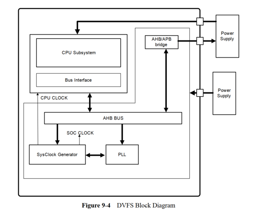
PLL provides a high-speed clock for the SysClock Generator, which uses a divider to generate the CPU CLOCK and SOC CLOCK.
To perform voltage and frequency scaling, the software first determines the minimum CPU clock speed required to meet workload demands. It then determines the minimum supply voltage that supports that clock speed.
If the target clock frequency is higher than the current frequency, the sequence of operations is as follows:
• The CPU programs the power supply to the new voltage
• The CPU subsystem continues to operate at the current clock frequency until the voltage stabilizes to the new value
• The CPU then programs the new clock frequency.
• If the change in clock frequency only requires changing the divider value, it will program the SysClock Generator for this new value. CPU operation does not need to be paused.
• If the new clock frequency requires changing the PLL frequency, the CPU will program the PLL to the new frequency. The PLL or SysClock Generator will suppress all clocks until the PLL stabilizes.
If the target clock frequency is lower than the current frequency, the sequence of operations is as follows:
• The CPU first programs the new clock frequency.
• If the change in clock frequency only requires changing the divider value, it will program the SysClock Generator for this new value. CPU operation does not need to be paused.
• If the new clock frequency requires changing the PLL frequency, the CPU will program the PLL to the new frequency. The PLL or SysClock Generator will suppress all clocks until the PLL stabilizes.
• The CPU then programs the power supply to the new voltage