Key Components of CAN Bus Systems and Solutions to Technical Failures

Key Components of CAN Bus Systems and Solutions to Technical Failures

1
CAN Bus
The Controller Area Network (CAN) is a serial communication network with a high level of safety that supports distributed real-time control. It first appeared in the automotive industry in the late 1980s. Its basic design specifications require high bit rates, strong electromagnetic interference resistance, and the ability to detect any errors that occur. The CAN bus system has a wide range of applications, from high-speed networks to low-speed networks, such as in automotive engine control units, ABS control units, sensors, etc. Its transmission speed can reach 1 Mbit/s, while the CAN bus system used for electric window control units has a transmission speed of no more than 125 kbit/s.
CAN’s high performance and reliability have been recognized and widely applied in industrial automation, marine, medical devices, and industrial equipment. Fieldbus technology is one of the hotspots in today’s automation technology development, hailed as the computer local area network of the automation field. Its emergence provides strong technical support for real-time and reliable data communication between nodes in distributed control systems.
2
Composition and Role of the CAN Bus System
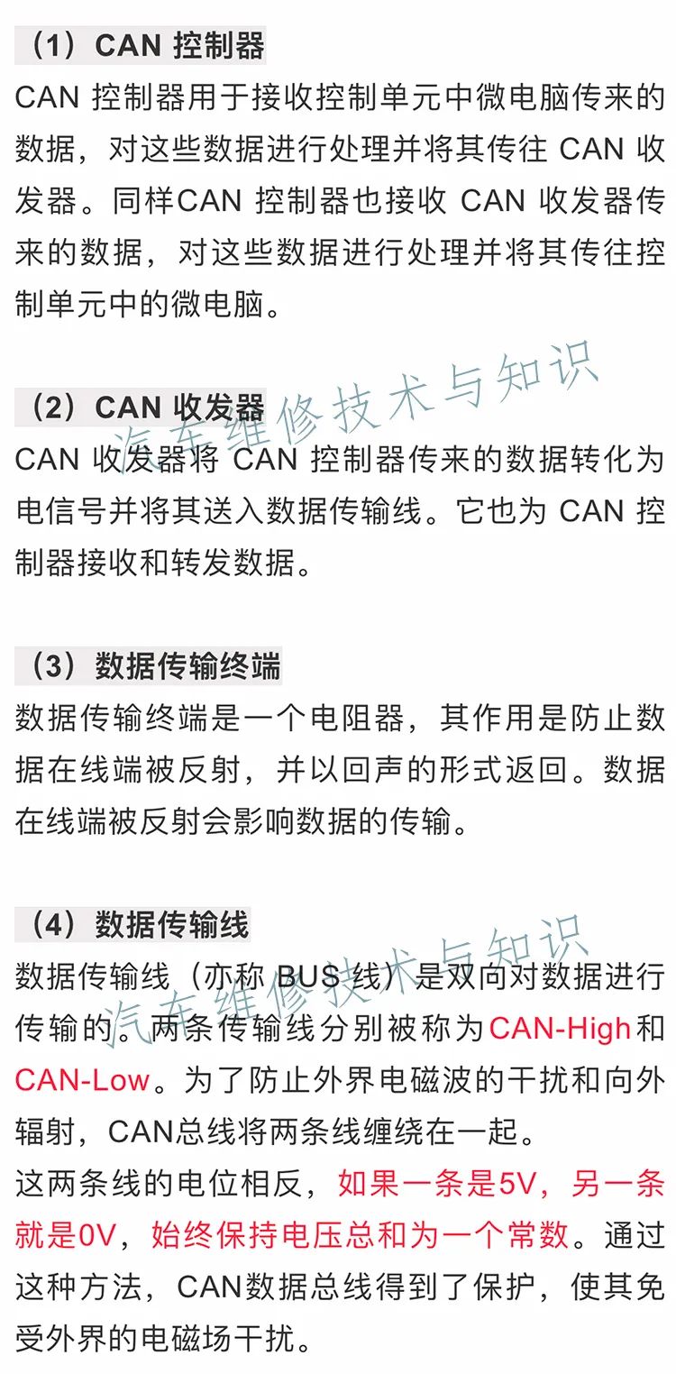
The CAN bus consists of a controller, a transceiver, two data transmission terminals, and two data lines. Except for the data transmission lines, the other components are placed inside the control unit. The functionality of the control unit remains unchanged.
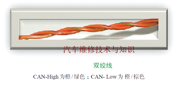
The CAN bus system uses twisted pair cables for data transmission. One of the wires is called the CAN-High wire, and the other is called the CAN-Low wire.
Key Components of CAN Bus Systems and Solutions to Technical Failures
On the twisted pair, the signals are transmitted in opposite phases, effectively suppressing external interference.
3
Key Components of the CAN Bus System
Key Components of CAN Bus Systems and Solutions to Technical Failures
4
Self-Diagnostic Function of the CAN Bus
■ The control unit has a self-diagnostic function, which can identify faults related to the CAN bus through this function.
■ After reading the CAN bus fault records with a diagnostic tool, one can quickly and accurately locate and eliminate faults based on the prompt information.
■ The fault records within the control unit are used for preliminary fault determination and can also be used to read the fault-free indication after troubleshooting, confirming that the fault has been resolved. If one wants to update the fault display content, the engine must be restarted.
■ The prerequisite for the normal operation of the CAN bus is that there should be no CAN bus fault records under any operating conditions of the vehicle.
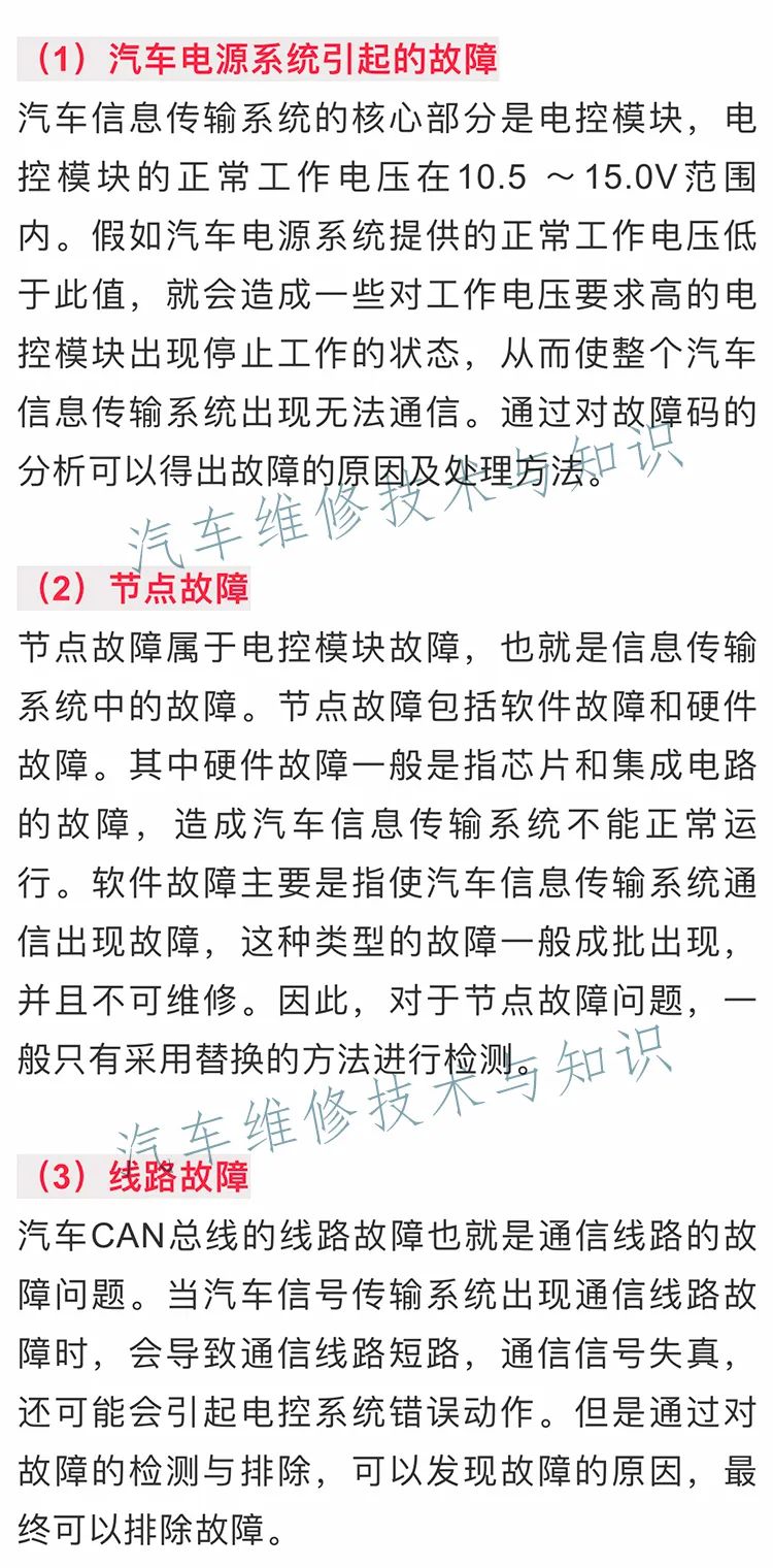
The CAN bus technology centralizes the wiring in the vehicle, reducing the occurrence of faults, and has a self-diagnostic function. There are three types of causes for faults in automotive information transmission:
Key Components of CAN Bus Systems and Solutions to Technical Failures
5
Solutions to Technical Failures of CAN Bus Technology
When a vehicle with a CAN bus experiences a fault, the first thing the automotive technician should check is whether the automotive information transmission system is functioning properly. If there is a fault in the information transmission system, the entire automotive information transmission system cannot operate normally, making fault diagnosis difficult. The CAN bus technology has a fault self-diagnostic mode, and the system reads the corresponding fault codes through self-diagnosis. For the repair of faults in the automotive CAN information transmission system, specific analysis and processing should be conducted based on the specific structure of the information transmission system.
Key Components of CAN Bus Systems and Solutions to Technical Failures
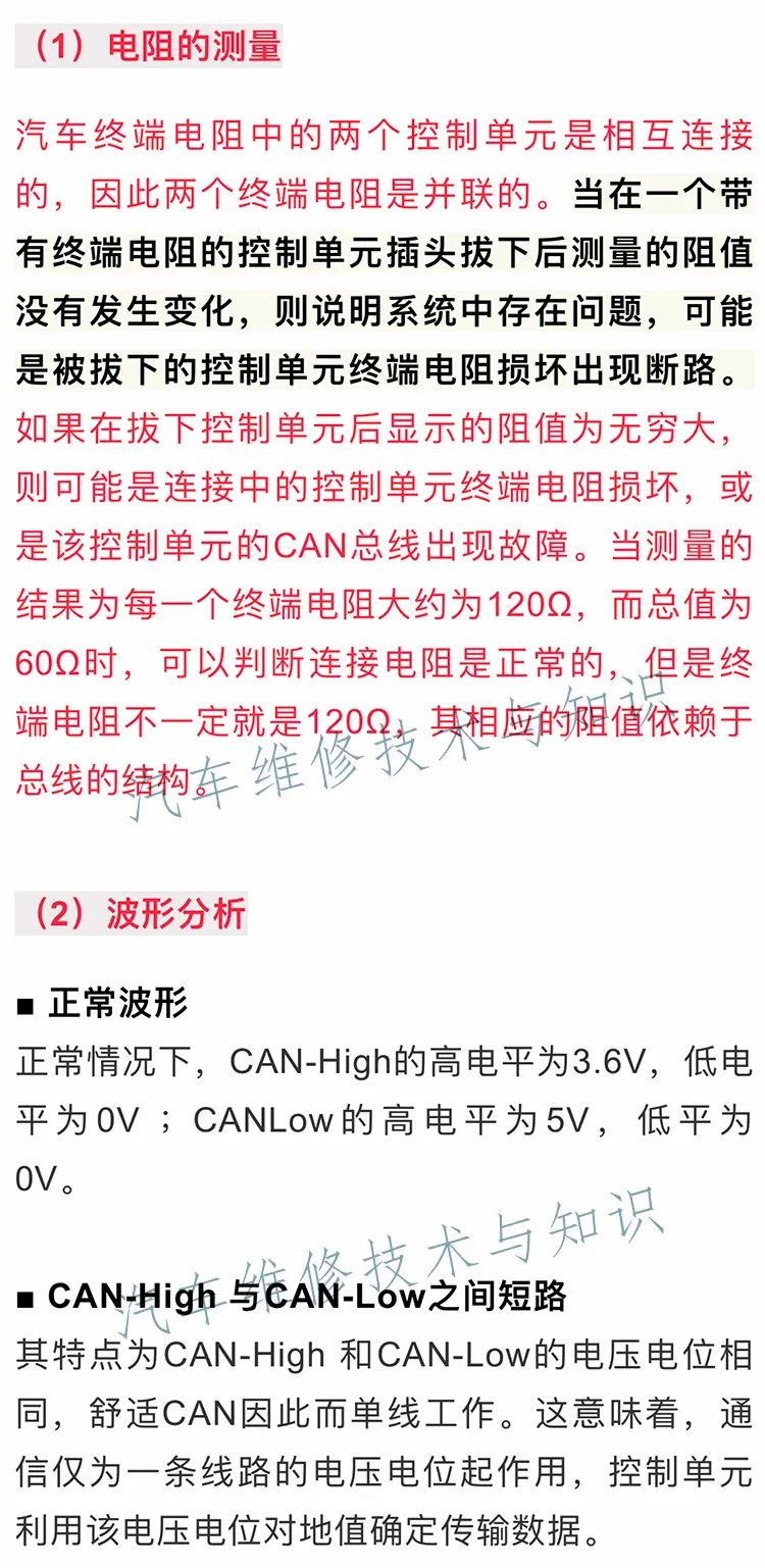
■ CAN-High Short Circuited to Ground
The characteristic is that the voltage of CAN-High is 0V, while the voltage potential of CAN-Low is normal. In this fault condition, the comfortable CAN operates in single-wire mode.
■ CAN-High Short Circuited to Positive
The voltage potential of CAN-High is approximately 12V or battery voltage, while the voltage potential of CAN-Low is normal. In this fault condition, the comfortable CAN operates in single-wire mode.
■ CAN-Low Short Circuited to Ground
The voltage of CAN-Low is 0V, while the voltage potential of CAN-High is normal. In this fault condition, the comfortable CAN operates in single-wire mode.
Key Components of CAN Bus Systems and Solutions to Technical Failures
This content is sourced from
Related Articles
more
  • Steps, Methods, and Precautions for CAN Bus Fault Diagnosis

  • Common Maintenance Methods for CAN Bus (Must-Have Tips)

  • Common Faults and Diagnosis Methods of FlexRay Bus Systems

  • Types of Automotive Buses, Fault Characteristics & Case Analysis

  • [Typical Cases] Automotive Bus Fault Repair Cases (3 cases)

  • Case Analysis of Air Conditioning Cooling Faults Caused by Automotive Buses (2 cases)

Key Components of CAN Bus Systems and Solutions to Technical Failures
Click below “Read Original” to join us for more!

Leave a Comment