Recently, while debugging the display issues in OpenHarmony, the cause was identified as the hardware being connected via HDMI to an RK628 adapter, which in turn connects to an LVDS display. The display panel implementation in OpenHarmony is relatively simple, directly using a DSI panel. Therefore, it is necessary to thoroughly organize the relevant drivers for the Harmony display panel.
1. Concept
For this scenario, we know that the focus is on the DRM panel and DRM bridge. Here’s an explanation:
-
DRM: The kernel DRM display framework, used for abstraction.
-
Panel: Refers to a screen, abstracted in DRM to represent a display, such as HDMI, LVDS, EDP, etc.
-
Bridge: Refers to a bridge concept, common in many bus architectures (PCIe), indicating the bridging of displays. Here, the HDMI to LVDS connected screen certainly involves the concept of a bridge.
For the RK3568, I illustrate it as follows:
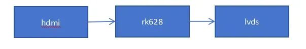
For us, we need to initialize the HDMI driver and enable HDMI as a bridge, then find the next bridge as RK628, and finally locate the actual panel on RK628.
2. Code Organization
2.1 drm_of_find_panel_or_bridge
This function should be emphasized for the scenario of solving this issue. It is a standard API provided by the kernel to find the next panel or bridge.
The function definition is as follows:
int drm_of_find_panel_or_bridge(struct device *dev, int port, int endpoint, struct drm_panel **panel, struct drm_bridge **bridge);
Here’s what needs to be explained:
- The first parameter is a pointer to the device.
- The second parameter is the port number in the device tree.
- The third parameter is the endpoint number in the device tree.
- The fourth parameter is a secondary pointer to the found panel.
- The fifth parameter is a secondary pointer to the found bridge.
The driver can use this function to obtain the next bridge or panel node from the device tree, thus triggering the component_ops bind callback.
2.2 Component
To clarify things, it is necessary to briefly introduce the component. For a detailed introduction, it is recommended to read the code.
Component is a component framework, usually implemented in larger kernel frameworks. The component framework is divided into master and component, with no significant difference; the master traverses all components according to match, and if all are registered, it triggers bind. Components can delay detection by returning -517, which is -DPROBE_DEFER.
Here, we take the display framework “display-subsystem” as the master, while other panels and bridges are registered as components. An example is as follows:
ret = component_master_add_with_match(dev, &rockchip_drm_ops, match);
component_add(&pdev->dev, &dw_hdmi_rockchip_ops);
2.3 Device Tree
For the device tree, we need to prepare the port and endpoint according to the actual hardware connection for the drm_of_find_panel_or_bridge function. I have organized it as follows:
hdmi:
   port@1 {
    reg = <1>;

    hdmi_out_hdmirx: endpoint {
     remote-endpoint = <&hdmirx_in_hdmi>;
     status = "okay";
    };
   };


rk628_hdmirx:
 ports {
  #address-cells = <1>;
  #size-cells = <0>;

  port@0 {
   reg = <0>;

   hdmirx_in_hdmi: endpoint {
    remote-endpoint = <&hdmi_out_hdmirx>;
   };
  };

  port@1 {
   reg = <1>;

   hdmirx_out_post_process: endpoint {
    remote-endpoint = <&post_process_in_hdmirx>;
   };
  };
 };


抽象rk628_post_process
 ports {
  #address-cells = <1>;
  #size-cells = <0>;

  port@0 {
   reg = <0>;

   post_process_in_hdmirx: endpoint {
    remote-endpoint = <&hdmirx_out_post_process>;
   };
  };
  port@1 {
   reg = <1>;

   post_process_out_lvds: endpoint {
    remote-endpoint = <&lvds_in_post_process>;
   };
  };
 };


rk628_lvds:
 ports {
  #address-cells = <1>;
  #size-cells = <0>;

  port@0 {
   reg = <0>;

   lvds_in_post_process: endpoint {
    remote-endpoint = <&post_process_out_lvds>;
   };
  };

  port@1 {
   reg = <1>;

   lvds_out_panel: endpoint {
    remote-endpoint = <&panel_in_lvds>;
   };
  };
 };


simple_panel:
  port {
   panel_in_lvds: endpoint {
    remote-endpoint = <&lvds_out_panel>;
   };
  };
To summarize the above code:
hdmi---->hdmirx_in_hdmi---->post_process_in_hdmirx---->lvds_in_post_process---->panel_in_lvds
3. Logical Summary
Based on the code organization above, we can understand the calling flow. Here’s a summary:
3.1 For the HDMI Driver:
component_add(&pdev->dev, &dw_hdmi_rockchip_ops);
A component is added, waiting for the bind call.
In dw_hdmi_bind, drm_bridge_attach is attached to DRM, and the next bridge is found through of_drm_find_bridge, where the next device is hdmirx_in_hdmi.
3.2 For the RK628_HDMIRX Driver:
drm_bridge_add adds the bridge device, and the attach callback is executed.
In the attach, the following is called:
drm_of_find_panel_or_bridge(dev->of_node, 1, -1, NULL, &hdmirx→bridge)
Then drm_bridge_attach is called.
Here, 1 and -1 refer to traversing from port 1 to find the endpoint, which is post_process_in_hdmirx.
3.3 For the RK628_Post_Process Driver:
Similarly,
drm_bridge_add adds the bridge device, and the attach callback is executed.
In the attach, the following is called:
drm_of_find_panel_or_bridge(dev->of_node, 1, -1, NULL, &pp→bridge)
Then drm_bridge_attach is called.
Here, 1 and -1 refer to traversing from port 1 to find the endpoint, which is lvds_in_post_process.
3.4 For the RK628_LVDS Driver:
Here, the panel device is directly searched in the probe function.
drm_of_find_panel_or_bridge(dev->of_node, 1, -1, &lvds->panel, NULL)
Then drm_bridge_add is called to add it.
3.5 For the Panel_Simple Driver:
Since this panel_simple driver is the DRM panel driver, it is responsible for initializing the panel with drm_panel_init and adding the panel with drm_panel_add.
4. OpenHarmony’s Approach
According to the display driver of OpenHarmony, the DSI hardware is directly initialized through the ili9881_st_5p5.c driver, and drm_panel_init and drm_panel_add are performed through hdf_drm_panel.c.
From the code, it can be seen that OpenHarmony does not involve the concept of a bridge. Therefore, based on the Linux display panel process, the ideal implementation of OpenHarmony’s HDF should be as follows:
- Implement the HDMI HDF driver based on the HDMI device tree.
- Find the bridge device under HDMI based on the DRM bridge concept.
- Initialize the RK628 driver based on the bridge device.
- Continue to find the panel device based on the RK628 driver.
- Implement the simple_panel driver to initialize the panel device.
We can skip steps 1, 2, 3, and 4, and only implement step 5 on OpenHarmony, allowing the driver to successfully traverse the DRM bridge or panel path during the component’s bind. This method can refer to the article “OpenHarmony-RK3568 Porting panel_simple_common”.
5. Personal Suggestions
Based on the above analysis, we know that if we want to design the HDF driver completely according to the HDF concept, we need to write many drivers for RK628 to achieve the basic functionality of HDF.
We can also base it on a principle:
DRM is an abstraction of the display framework, which includes CRTC, plane, connector, encoder, framebuffer, panel, and bridge. Generally, Harmony calls through libdrm and does not involve panels and bridges, which are separated from CRTC. Therefore, the panels and bridges based on DRM do not necessarily need to be implemented using HDF; we can borrow the implementation from Linux.
As for CRTC and others, based on code tracing, Harmony’s hdf_disp has not implemented the entire set of DRM functionalities.
Thus, the hdf_disp driver is actually incomplete; it only implements the panel, and the bridge has not even been implemented. Therefore, my suggestion is that the display driver can temporarily use the standard Linux implementation.
For references on hdf_disp calling DRM, see the article “OpenHarmony-RK3588-drm_plane Settings”.
From the analysis of the above article “OpenHarmony-RK3588-drm_plane Settings”, it can be concluded that the display in HDF is not critical, so we can fully use the Linux implementation. The method is as follows:
5.1 Display Based on DRM (Non-HDF)
Modifying based on the Linux method is straightforward; for DRM display, we need to perform the following operations:
5.1.1 Modify defconfig
For the already compiled kernel, we modify the<span>arch/arm64/configs/rockchip_linux_defconfig</span> file. For the uncompiled kernel, we modify the<span>kernel/linux/config/linux-5.10/arch/arm64/configs/rk3568_standard_defconfig</span>
We add the following at the bottom:
# CONFIG_DRIVERS_HDF_DISP is not set
CONFIG_DRM_PANEL_SIMPLE=y
5.1.2 Modify Plane Layer
For the device tree, we refer to “OpenHarmony RK3568 Layer Settings” for modifications, adding the following:
&vp0 {
        rockchip,plane-mask = <(1 << ROCKCHIP_VOP2_CLUSTER0 | 1 << ROCKCHIP_VOP2_ESMART0 | 1 << ROCKCHIP_VOP2_SMART0)>;
        rockchip,primary-plane = <ROCKCHIP_VOP2_ESMART0>;
        cursor-win-id = <ROCKCHIP_VOP2_CLUSTER0>;
};
At this point, all relevant modifications are complete. Compile the kernel to verify, and under these conditions, the RK3568 device based on OpenHarmony’s kernel can display normally.
# Building a World-Class Operating System
We invite comments and likes, thank you!!!
For other articles, please follow the public account: Kirin Embedded