Click the blue text to follow us
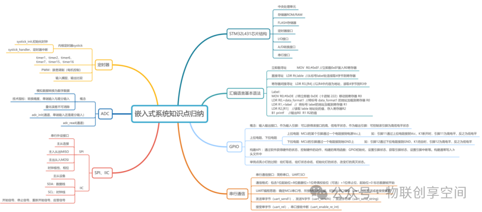
The summary of embedded system knowledge points (taking the STM32L431 chip as an example) is divided into the following main modules: basic concepts of embedded systems, components of embedded products centered around MCUs, internal hardware modules of MCUs, commonly used assembly data operation instructions, specific processes of embedded development, and the knowledge map of embedded development. Below is a detailed introduction:
1
Basic Concepts of Embedded Systems

An embedded system is a combination of computer hardware and software, possibly including mechanical devices, designed to perform a specific function.
2
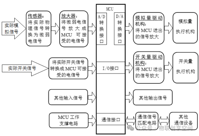
Components of Embedded Measurement and Control Products Centered Around MCUs
3
Internal Hardware Modules of MCUs
(1) GPIO: General Purpose Input/Output – General input/output interface
(2) RAM: Random Access Memory – Random access memory
(3) ROM: Read Only Memory – Read-only memory
(4) UART: Universal Asynchronous Receiver/Transmitter – Universal asynchronous transceiver
(5) PWM: Pulse Width Modulation – Pulse width modulation
(6) FLASH: Flash Memory – Flash memory (specifically refers to non-volatile memory used in embedded systems to store program code and data)
(7) Timer: Timer – Timer/counter
(8) SysTick: System Tick Timer – System tick timer (standard timer in ARM Cortex-M core)
(9) DMA: Direct Memory Access – Direct memory access
(10) CAN: Controller Area Network – Controller area network
(11) 12-bit A/D: 12-bit Analog-to-Digital Converter – 12-bit analog-to-digital converter
(12) RTC: Real-Time Clock – Real-time clock
(13) Input Capture: Input Capture – Input capture (a function of the timer used to capture the moment when external signal edges occur)
(14) SPI: Serial Peripheral Interface – Serial peripheral interface
(15) I2C: Inter-Integrated Circuit – Integrated circuit bus (also often written as I²C)
(16) TSC: Touch Sensing Controller – Touch sensing controller (this abbreviation is commonly found in STMicroelectronics MCUs, used for capacitive touch detection)
4
Commonly Used Assembly Data Operation Instructions
(1) AND: AND (Bitwise AND) – Logical AND
AND AL, 0F0H ; Keep the high 4 bits of AL, clear the low 4 bits
(2) LDR: Load Register – Load register
LDR Rt,label ; Load 4 bytes from label into the register
(3) LDRH: Load Register Halfword – Load register (halfword)
LDRH Rt,label ; Read halfword from address label into Rt
(4) STR: Store Register – Store register
STR R3, =0x2000 ; Store 0x2000 into R3
(5) ASR: Arithmetic Shift Right – Arithmetic right shift
ASR R3, R2, #16 ; Sign extend 16-bit number to 32 bits:
R3 = 0xFFFF8000
(6) ORR: OR Register (Bitwise OR) – Logical OR
ORR R0, R0, #0x8 ; Set the 3rd bit to 1 → R0 = 0b0000_1000 (0x08)
(7) SUB: Subtract – Subtraction
MOV EAX, 10
SUB EAX, 3 ; EAX = 10 – 3 = 7
(8) CMP: Compare – Comparison
MOV R1, #20
CMP R1, #15 ; Compare R1 and 15
BGT greater ; If signed R1>15 then jump (N==0 and Z==0)
(9) MUL: Multiply – Multiplication
MUL R0, R1, R2 ; R0 = R1 × R2 (only keep the low 32 bits)
5
Specific Process of Embedded Development
(Taking controlling a pin to light up a lamp as an example)
(1) Module Initialization
Void gpio_init(uint16_t port_pin,uint8_t dir,uint8_t state);
(2) Set Pin Mode (Input, Output, Analog)
Void gpio_pull(uint16_t port_pin, uint8_t pullselect);// Input pull-up
(3) Get Pin Status/Control Pin Status
Void gpio_get(uint16_t port_pin);
Void gpio_set(uint16_t port_pin,uint8_t state);
6
Knowledge Map of Embedded Development