1. Versions of ESP32

1. Classic Basic Model (Core Chip + General Module): ESP32-D0WD/D0WD-V3, ESP32-WROOM-32E/32UE.
2. Low-Cost Simplified Model: ESP32-SOLO-1, ESP32-C3, ESP32-C2.
3. Small Size High Integration Model: ESP32-PICO-D4, ESP32-PICO-MINI-02.
4. Performance Enhanced Model: ESP32-S3, ESP32-WROVER-E/IE.
5. New Protocol Adaptation Model: ESP32-C6, ESP32-D2WD, ESP32-S2.
6. Low Power Special Model: ESP32-D2WD, ESP32-S2.

2. Preparation for Getting Started
01
Hardware Selection

Recommended Development Boards:
ESP32-DevKitC: Basic model, suitable for beginners, with all pins exposed.
ESP32-C3-DevKitM-1: Smaller size, low power, suitable for portable devices.
NodeMCU-32S: Compatible with NodeMCU layout, comes with USB-TTL chip, plug and play.
Other Tools:
Micro-USB data cable (for power and programming)
Computer (compatible with Windows/macOS/Linux)
02
Setting Up the Development Environment

It is recommended that beginners use Arduino IDE (simple and easy to use), the steps are as follows:
1. Download and install Arduino IDE from the official website: https://www.arduino.cc/en/software, follow the prompts to install.
2. Add ESP32 board support
(1)Open Arduino IDE, click “File” → “Preferences” → “Additional Board Manager URLs”, add: https://dl.espressif.com/dl/package_esp32_index.json
(2)Click “Tools” → “Board” → “Board Manager”, search for “esp32”, and install “ESP32 by Espressif Systems” (latest version is fine).
3. Select the board and port
(1)Connect the ESP32 development board to the computer, select the corresponding model in “Tools” → “Board” (e.g., “ESP32 Dev Module”).
(2)Select the connected serial port in “Tools” → “Port” (e.g., COMx on Windows, /dev/cu.usbserial-xxx on macOS).

3. Try Your First Program to Light Up an LED
01
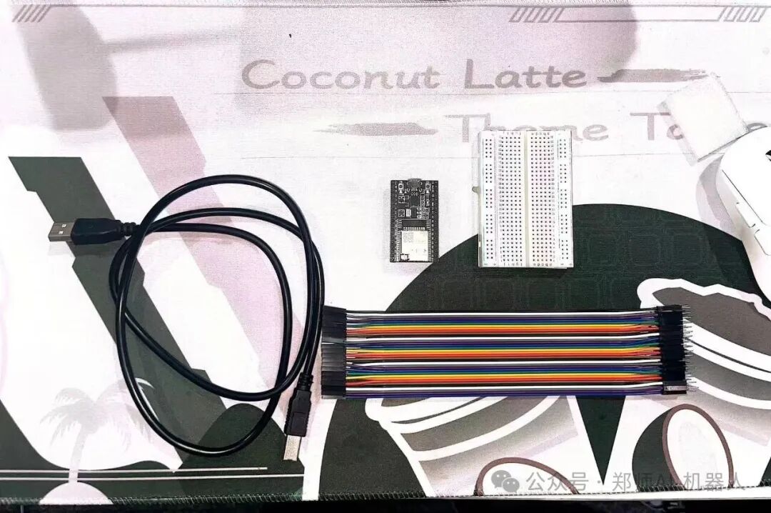
Required Hardware

1. ESP32 development board (e.g., NodeMCU-32S or ESP32-DevKitC)
2. One each of red, yellow, and green LEDs
3. One 220Ω resistor (current limiting, to protect the LED and ESP32 pins)
4. One breadboard
5. Several Dupont wires
6. Micro-USB data cable (for power and programming)
02
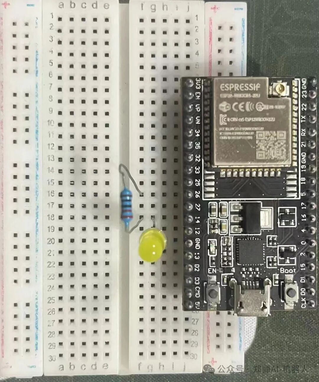
Circuit Connection

1. The GPIO pins of the ESP32 can output a high level of 3.3V, controlling the LED to turn on and off. The connection method is as follows:
2. The long leg of the LED (anode) → in series with a 220Ω resistor → connect to the GPIO pin of the ESP32 (recommended pin: red – 13, can be customized).
3. The short leg of the LED (cathode) → connect to the GND of the ESP32 (ground).
03
Upload and Test

1. Connect the ESP32 to the computer, select the correct board (e.g., “ESP32 Dev Module”) and port in Arduino IDE.
2. Edit the code according to the prompts on the official website. (As shown in the figure below)
3. Click the “Upload” button and wait for the compilation and upload to complete.
4. After successful upload, the red and green lights will cycle according to the set timing: LED lights up for 0.5 seconds → off for 3 seconds.
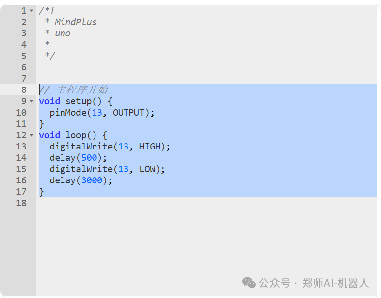


Image source: Liang Zhuang
Copy design: Dong Jinjia
Content review: Chen Weiguang