Introduction to Diagnosing PROFINET IO Using SFC51/SFB52/SFB54
1 Solution 1.1 Project Introduction Figure 1 PROFINET IO network topology for diagnosing SFC51/SFB52/SFB54. The CPU319-3PN/DP serves as the IO controller, with SCALANCE X switches and ET200S, ET200Eco connected as IO devices. ……
1 Solution
1.1 Project Introduction
Figure 1 PROFINET IO network topology for diagnosing SFC51/SFB52/SFB54. The CPU319-3PN/DP serves as the IO controller, with SCALANCE X switches and ET200S, ET200Eco connected as IO devices.
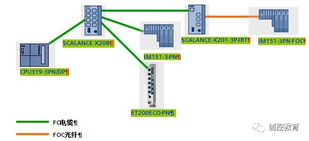
Figure 1 PROFINET IO network topology
The main hardware and software used in this example are as follows:
Name Quantity Version Order Number CPU319-3PN/DP 1 V2.8 6ES7 318-3EL00-0AB0 SCALANCE X208 1 V4.0 6GK5 208-0BA10-2AA3 SCALANCE X201-3P IRT 1 V4.1 6GK5 201-3BH00-2BA3 IM151-3 PN 1 V6.1 6ES7 151-3BA23-0AB0 IM151-3 PN FOC 1 V4.0 6ES7 151-3BB21-0AB0 PM-E 2 6ES7 138-4CA01-0AA0 2DO HF 2 6ES7 132-4BB01-0AB0 ET200 eco PN 1 6ES7 142-6BG00-0AB0 Step7 1 V5.4+SP5
1.2 Hardware Configuration
Configure the hardware in Step7 according to section 1.1. Then assign device names and download the configuration data to CPU319. For specific settings of device names and completing PROFINET communication, please refer to the website download center “S7-300 PROFINET IO Communication Quick Start” 72325620
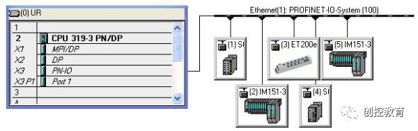
Figure 2 Hardware configuration in Step7
In this, the “Ethernet(1):PROFINET-IO-System(100)” bus indicates the sequence number of the PROFINET bus. IO devices such as SCALANCE X and ET200 range from 1 to 5, indicating the device numbers of PROFINET IO.
2 SFC51 Diagnosis
2.1 Introduction
The System Status List (SSL) describes the current state of the programmable logic controller. The contents of the SSL can only be read via system functions and cannot be modified. In other words, some lists are virtual lists, created by the CPU’s operating system only upon special requests.
SFC 51 “RDSYSST” system function is used to read the “System Status List” (abbreviated as SSL), including partial lists or excerpts from the CPU’s SSL list. For PROFINET IO, these SSLs contain status information of I/O modules, the PROFINET IO master system, or the actual controller. When selecting the SSL ID used, especially in an interrupt or startup OB, it must be noted that SFC can only be executed synchronously. If the Busy bit is activated after executing SFC, it indicates that SFC is executed multiple times in a few cycles, and data has not been fully read out, thus the data is invalid. The received system status list data records include an overview of diagnostic information on PROFINET IO devices.
The PN communication partial list is a virtual list, created by the CPU’s operating system only upon requests. The virtual list comes from the buffer of the PN IO controller inside the CPU, which is maintained and refreshed by the controller’s startup and ALARM information.
SSL_ID for PROFINET IO diagnostics includes:
SSL_ID (W#16#…) Partial List (PROFINET) INDEX (W#16#…) 0C91 Module status information on the PROFINET interface module (integrated or external) Logical base address, output module bit15=1 0D91 Module status information of all modules in PROFINET bits 0 to 10: station number, bits 11 to 14: last two digits of PN IO system bus number, Bit 15: 1 0094 Expected status of the station on PROFINET interface module (integrated or external) 100-115: PN IO system bus number 0294 Read whether the actual site exists Same as above 0694 Read whether the actual site has errors Same as above 0794 Read the maintenance status of the actual site Same as above 0C96 Module status information of all modules in PROFINET Logical base address, output module bit15=1 The SFC51 can only obtain the status information of a station or module, such as a lost station or an error in the module, but cannot obtain detailed information about the failure of the template, such as which channel of the template is broken or short-circuited.
2.2 Programming
Here, SFC51 is used to read the actual status of each station to determine whether a station has lost connection. An empty OB86 is added and downloaded in the PLC to prevent CPU shutdown during loss testing. Of course, OB86 can also be used to read the actual status of each IO device, but more programming is required. For information on using OB86 to obtain IO station status, please refer to the website download center “Using OB8x to Diagnose SIMATIC PLC (PN)” 87668286
In OB1, add SFC51, for parameter settings, click “F1” to refer to the online help for SFC51. Example program is as follows:
CALL "RDSYSST"<br />REQ :=M0.0<br />SZL_ID :=MW2<br />INDEX :=MW4<br />RET_VAL :=MW6<br />BUSY :=M0.1<br />SZL_HEADER:=DB1.SSL_HEADER<br />DR :=DB1.RECORDSet SSL_ID=0294 (MW2) and INDEX=16#64 (MW4) in the variable table according to the above table, where 16 hexadecimal 64 in decimal is 100, indicating the sequence number of the PROFINET bus, please refer to Figure 2 Hardware configuration in Step7. Add the variables to be viewed and enable M0.0 to be 1. The number of data records read is 1 (DB1.DBW2), the length of this data record is 258 bytes (DB1.DBW0). DB1.DBW4 indicates the sequence number of the PROFINET bus, which is 100 (64H). For DB1.DBB6, it is 2#0011_1111, where bit0 indicates group information; if it is 1, it indicates at least one IO device is communicating with the IO controller; if 0, it indicates all IO stations are lost. Bits 1 to 5 indicate the status of IO devices numbered 1 to 5, where 1 indicates the IO device exists, and 0 indicates the IO device has lost connection. Other Bits and high byte Bits follow suit, indicating the status of corresponding IO devices.
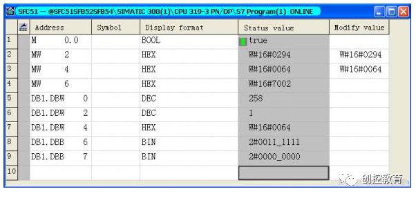
Figure 3 Viewing device status according to the variable table
Based on these bits Bit1~5, it is very convenient to display on WinCC/WinCC Flexible or any third-party HMI communicating with the PLC, facilitating quick detection and maintenance of field faults.
3 SFB52 Diagnosis
3.1 Introduction
The SIMATIC S7 diagnostic data records provide additional detailed diagnostic performance. The system function block SFB 52 “RDREC” is used to read these data records.
When called, the system function block addresses the station ID to be diagnosed and indicates the data record to be read with the INDEX parameter. This may be a module in the central rack or distributed components (PROFIBUS DP or PROFINET IO). If there is no diagnostic information, there will be no output after the execution of the system function block. Since SFB 52 “RDREC” is an asynchronous executing SFB, the execution process spans several SFB calls, thus this block can only be used in cyclic operations. It cannot be used in diagnostic OB or timed interrupt OB. In addition to the exact location of the error, SFB 52 diagnostic data records also contain information about the type of error that occurred. For further analysis, this information can be evaluated.
The maximum number of bytes to read is specified in MLEN. The selected length of the target area RECORD should be at least equal to the length of MLEN bytes. If the output parameter VALID is TRUE, it indicates that the data record has been successfully transferred to the target area RECORD. At this point, the output parameter LEN contains the length of the acquired data (in bytes). The output parameter ERROR indicates whether a data record transfer error has occurred. If an error occurs, the output parameter STATUS contains the error information.
This function block belongs to the state-driven type and can be called in OB1 or other cyclic OB blocks for reading diagnostic records or configuration records and other data records.
The PROFINET IO device model describes the structure of modular and compact field devices. It is built based on the fundamental characteristics of PROFIBUS DP. Definitions of submodules and APIs have been added to the device model to enhance the flexibility of IO devices.
A PROFINET IO device includes one or more “logical devices,” which in turn contain one or more APIs (Application Process Identifiers), with at least API 0.
The characteristics of the device are described by the XML-based GSD (General Station Description) file of the IO device. The GSDXML file can be read using the PROFINET XML Viewer.
Involving the concept of hierarchy, AP, API, SLOT, SUBSLOT. Each addressing level has a set of available diagnostic records and configuration records. The diagnostic level of each record group is distinguished by the first letter of the record number, as shown in Figure 4 Diagnostic Level. For more information on the PROFINET IO device model and the structure of diagnostic data records, please refer to 19289930
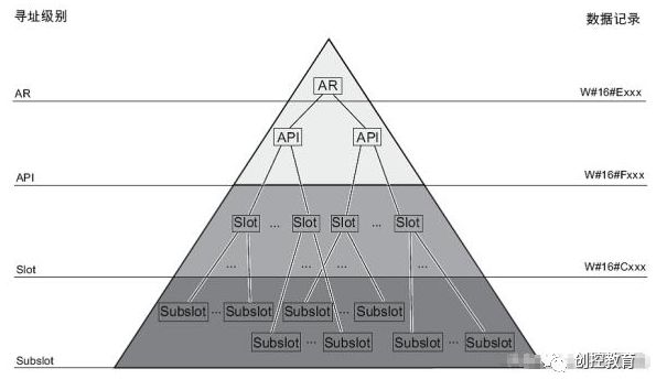
Figure 4 Diagnostic Level
3.2 Programming
Here, SFB52 is used to read the status of the output module of the ET200S IM151-3PN FOC site, such as disconnection, refer to Figure 5 Hardware configuration list of ET200S FOC. An empty OB82 is added and downloaded in the PLC to prevent CPU shutdown during disconnection testing. Of course, OB82 can also be used to read the module status information of the IO device, but more programming is required. For information on using OB82 to obtain the module status information of the IO station, please refer to the website download center “Using OB8x to Diagnose SIMATIC PLC (PN)” 87668286
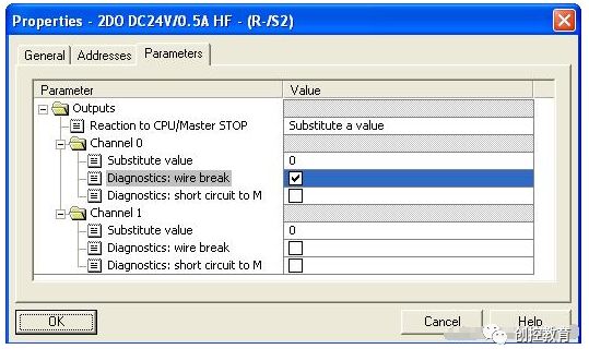
Figure 5 Hardware configuration list of ET200S FOC
Double-click the 2DO DC24V/0.5AHF template of this station, set to enable the diagnosis of disconnection related to channel 0, refer to Figure 6 Parameter settings of ET200S 2DO module.
Figure 6 Parameter settings of ET200S 2DO module
Add SFB52 in OB1, for parameter settings, click “F1” to refer to the online help for SFB52. Example program is as follows:
CALL “RDREC” , DB52
REQ :=M0.2
ID :=MD8
INDEX :=MW12
MLEN :=MW14
VALID :=M0.3
BUSY :=M0.4
ERROR :=M0.5
STATUS:=MD18
LEN :=MW22
RECORD:=DB2.DB_RECORD
Set ID=16#00008002 (MD8) and INDEX=16#800A (MW12) in the variable table as needed, where 8002 indicates the logical address of this output template, please refer to Figure 4 Hardware configuration list of ET200S FOC. Add the variables to be viewed and enable Q2.0 to be 1, at this time activate the disconnection fault, the DO template, ET200S FOC interface template, and the SF light of the CPU are on. Set the data length of MLEN (MW14) to 100, which needs to be greater than or equal to the actual length of the data record read, otherwise, relevant diagnostic information cannot be read. Then enable M0.2 to be 1, the data record read is as shown in Figure 7 Diagnostic data record. Among them, the last word DB2.DBW24 is 16#0006, indicating that a “disconnection” fault occurred in channel 0 (DB2.DBW20) of slot 2 (DB2.DBW10) and subslot 1 (DB2.DB14) of this station, refer to Figure 8 ChannelErrorType coding. For more detailed channel fault type information, please refer to 19289930
It is also possible to diagnose at a higher level, such as the AR level, setting ID=16#00001FDF (MD8) for the diagnostic address of the interface template and INDEX=16#E00A (MW12) can also read the same diagnostic data records, but since this level is the highest, it can obtain detailed diagnostic information for each template and channel of the station.
Based on the coding of fault types, it is very convenient to set and display diagnostic information on WinCC/WinCC Flexible or any third-party HMI communicating with the PLC, facilitating quick detection and maintenance of field faults.
It should be noted that when calling SFB52 in Step7, do not continuously trigger REQ, that is, REQ should not always be 1; it is best to call this function block when needed, as continuous triggering will occupy more resources and bandwidth from the PLC.
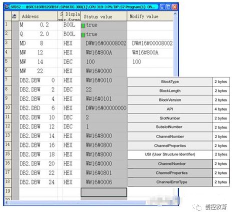
Figure 7 Diagnostic data record
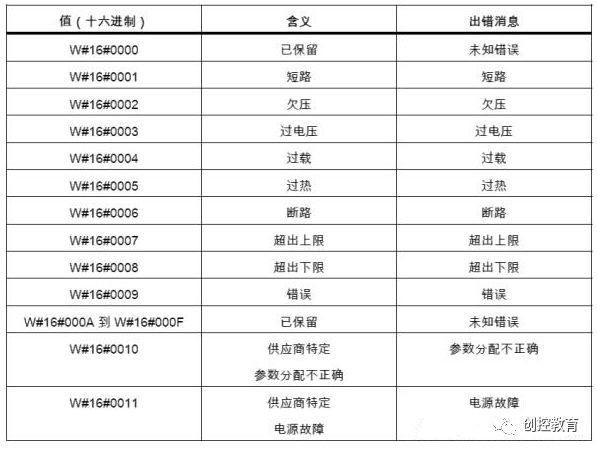
Figure 8 ChannelErrorType coding
4 SFB54 Diagnosis
4.1 Introduction
SFB “RALRM” receives interrupts and all corresponding information from peripheral device modules (centralized structure) or from DP slaves or PROFINET IO device components.
It then provides this information through the output parameters.
The information contained in the additional detailed output parameters includes the startup information of the called OB and the information of the interrupt source. Since it is necessary to check the peripheral device interrupts, SFB 54 can only be called in interrupt OBs initiated by the CPU’s operating system. Calling SFB 54 “RALARM” outside of interrupt OBs is not recommended, as important diagnostic state information cannot be obtained at that time.
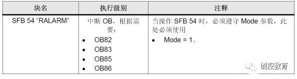
In the TINFO and AINFO data cache, when USI=16#8000 (WORD 26) in AINFO, some important information for quick diagnosis is as follows:
TINFO’s WORD 20 Station number.
AINFO’s WORD 4 Interrupt type
WORD 12 Slot number (SLOT)
WORD 28 Channel number (CHANNEL)
WORD 32 Error type
4.2 Programming
Here, SFB54 is used to capture the interrupt status of the output module of the ET200S IM151-3PN FOC site, such as disconnection, refer to Figure 5 Hardware configuration list of ET200S FOC. Add SFB54 in OB82 to capture disconnection faults. Of course, OB82 can also be used to read the module status information of the IO device, but more programming is required. For information on using OB82 to obtain the module status information of the IO station, please refer to the website download center “Using OB8x to Diagnose SIMATIC PLC (PN)” 87668286
Double-click the 2DO DC24V/0.5AHF template of this station, set to enable the diagnosis of disconnection related to channel 0, refer to Figure 6 Parameter settings of ET200S 2DO module.
In OB82, add SFB54, for parameter settings, click “F1” to refer to the online help for SFB54. Example program is as follows:
L #OB82_MDL_ADDR
T MD 30
CALL “RALRM” , DB54
MODE :=1
F_ID :=MD30
MLEN :=1000
NEW :=M1.0
STATUS:=MD36
ID :=MD40
LEN :=MW44
TINFO :=”TINFO”.TINFO
AINFO :=”AINFO”.AINFO
Add TINFO and AINFO data records in the variable table. Among them, TINFO’s WORD20 is 8005, indicating that fault occurred at station number 5 in the system with PROFINET bus sequence number 100. According to Figure 9 AINFO variable table, AINFO’s DB4.DBW32 is 16#0006, indicating that a “disconnection” fault occurred in channel 0 (DB4.DBW28) of slot 2 (DB4.DBW12) and subslot 1 (DB4.DBW14) of this station, refer to Figure 8 ChannelErrorType coding. For more detailed channel fault type information, please refer to 19289930
Figure 9 AINFO variable table
Based on the coding of fault types, it is very convenient to set and display diagnostic information on WinCC/WinCC Flexible or any third-party HMI communicating with the PLC, facilitating quick detection and maintenance of field faults.
(Content sourced from the internet, copyright belongs to the original author)
Disclaimer:If copyright issues arise, please contact for removal!
No one and no organization bears related legal responsibilities.
Recommended Reading:
Benefits Coming! Schneider SoMachine Course Free Learning
The first batch of IAAT certificates has been issued, please check, engineers!
Summary of RS485 and Modbus Communication Protocols, everything you want is here!
For detailed course inquiries:
Teacher Cheng 15315136942 (same number on WeChat)
Technical communication group:536682860 (QQ group)