Introduction to Assembly Language Programming for Microcontrollers

Click the blue text to follow us

Introduction to Assembly Language Programming for Microcontrollers

1. Overview of Microcontroller Programming Languages

1. Three commonly used programming languages for microcontrollers

Machine Language
Refers to programming directly using machine code, which can be executed directly by the computer.
Assembly Language
Refers to programming languages that use mnemonic codes to replace machine code.
High-Level Language

The widely used high-level language is C. Whenever a new type of microcontroller is released, there is a corresponding C compiler to support it. The drawback of programming in high-level languages is that it is not real-time, the structure is not compact, and the compiled code occupies a relatively large amount of storage space, which is a disadvantage in microcontroller application systems with limited memory.

2. Types and Formats of Assembly Language Statements
(1) Types of Instructions
  • Instruction Statements
Each instruction statement generates an instruction code—machine code—during assembly.
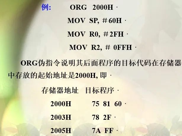
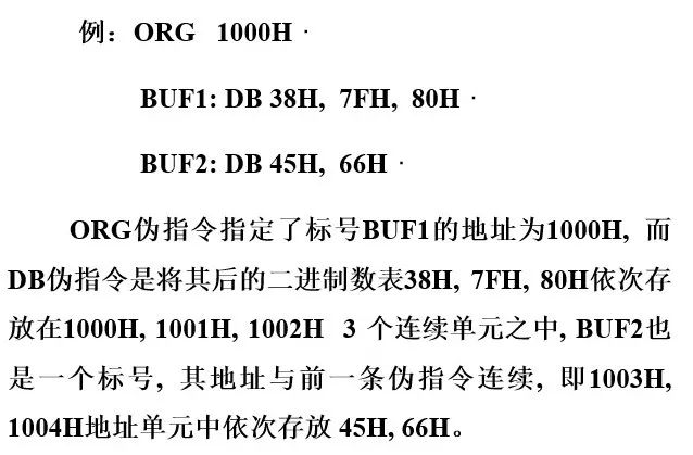
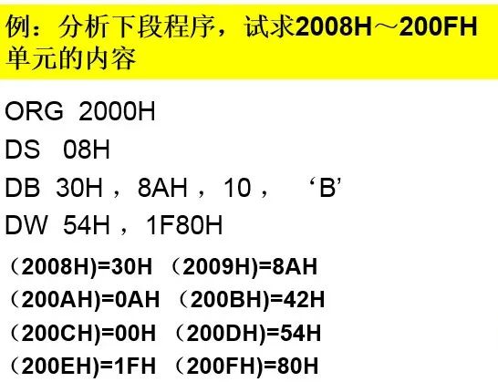
  • Pseudoinstruction Statements
Pseudoinstruction statements are for assembly purposes. They do not correspond to any machine code during assembly. Pseudoinstruction statements control how the assembly program completes its work, including controlling the assembly program’s input/output, defining data and symbols, conditional assembly, allocating storage space, etc. This information is the pseudoinstruction.
3. Pseudoinstruction
Controls the assembly process but does not have a corresponding machine code instruction.
(1) Assembly Start Instruction ORG
Instruction format: ORG nn
This instruction indicates the starting address of the subsequent program or data block; it always appears at the beginning of each segment of source program or data block. In the format, nn is a 16-bit address. During assembly, nn determines the address of the first instruction or first data following this statement, and subsequent source programs or data blocks are stored consecutively in the following addresses until another ORG instruction is encountered.

Introduction to Assembly Language Programming for Microcontrollers

(2) Equivalence Instruction EQU

Instruction format: Character Name EQU Number or Assembly Symbol

Example: PA8155 EQU 8001H ; assigns the value 8001H to the label PA8155

This makes the character name in the instruction equivalent to the given number or assembly symbol.

If a certain address is to be used multiple times in the program, the EQU instruction assigns it a character name, and once a change is needed, simply change the number after the EQU command.

Note: The character names equivalent to EQU must be assigned values before use, and in the same source program, the same label can only be assigned once.

(3) Define Byte Instruction DB
Instruction format: [Label: ] DB 8-bit binary number table
Function: Stores the 8-bit binary number table sequentially into consecutive memory units starting from the label.
The label section is optional; the 8-bit binary number table after the DB instruction can be a byte constant or a comma-separated byte string, or it can be an ASCII code string enclosed in quotes (one ASCII character corresponds to one byte).

Introduction to Assembly Language Programming for Microcontrollers

(4) Define Word Instruction DW
Instruction format: [Label:] DW 16-bit data table
This instruction functions similarly to DB, with the only difference being that it stores the 16-bit data from the specified address, rather than a byte string. Each 16-bit data occupies two memory units, with the high 8 bits stored first, followed by the low 8 bits, which is consistent with the 16-bit data storage order in MCS-51 instructions.
DS Define Storage Space Command
Format:DS Expression
Function: During assembly, reserves the storage units specified by the value of the expression after DS starting from the specified address for future use.
For example: ORG 1000H
DS 08H
DB 30H,8AH
After assembly, 8 units are reserved starting from 1000H, and then from 1008H, memory is assigned values according to the DB command,
that is, (1008H)=30H (1009H)=8AH
BIT Bit Address Symbol Command
Format:Character Name BIT Bit Address
Function: Assigns the bit address value after BIT to the character name. The character name is not a label and has no colon after it, but the character name is mandatory.
For example: A1 BIT P1.0
A2 BIT 02H
After assembly, the bit address 90H of port P1.0 is assigned to A1, while A2’s value is 02H.

Introduction to Assembly Language Programming for Microcontrollers

(5) Assembly End Instruction END
Instruction format: [Label:] END Address or Label
The label in the format and the address or label after END can be optional.
Function: Provides an assembly end marker. The assembly program stops assembling when it encounters END, and does not process statements after END, so END should be placed at the end of the program.

2. Basic Structure of Assembly Language

1. Sequential Program Design

Example 1: Adding two unsigned double-byte numbers.

Assume the addend is stored in internal RAM at 40H (high byte), 41H (low byte), and the adder is stored at 50H (high byte), 51H (low byte), with the sum stored in 40H and 41H units.

The program is as follows:

ORG 0000H

JMP START

ORG 0100H

START: CLR C ; Clear Cy

MOV R0, #41H ; Load the address of the addend into data pointer R0

MOV R1, #51H ; Load the address of the adder into data pointer R1

MOV A, @R0 ; Load the content of the low byte of the addend into A

ADD A, @R1 ; Add the two low bytes

MOV @R0, A ; Store the sum of the low byte into the low byte of the addend

DEC R0 ; Point to the high byte of the addend

DEC R1 ; Point to the high byte of the adder

MOV A, @R0 ; Load the high byte of the addend into A

ADDC A, @R1 ; Add the two high bytes with Cy

MOV @R0, A ; Store the sum of the high byte into the high byte of the addend

END

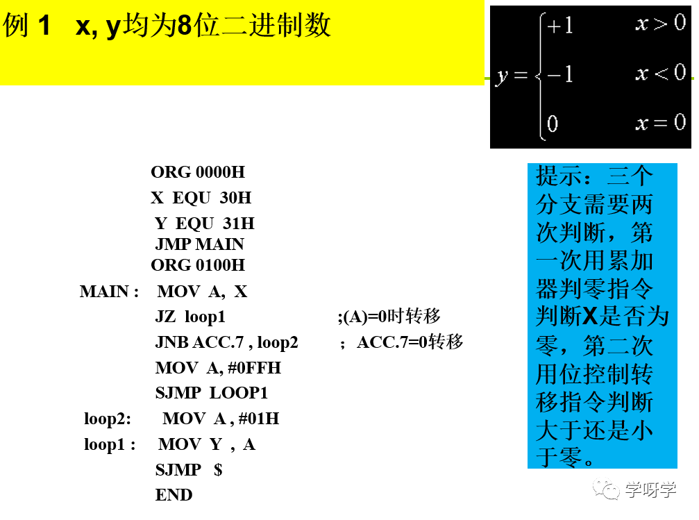
2. Branch Program Design

  • Implementing branches: Conditional transfer instructions

    Accumulator zero check instructions JZ/JNZ

    Comparison transfer instruction CJNE

    Bit control transfer instructions JC/JNC/JB/JNB/JBC

  • Control each branch: Unconditional transfer instructions

    LJMP/AJMP/SJMP/JMP

Introduction to Assembly Language Programming for Microcontrollers

3. Loop Program Design

Introduction to Assembly Language Programming for Microcontrollers

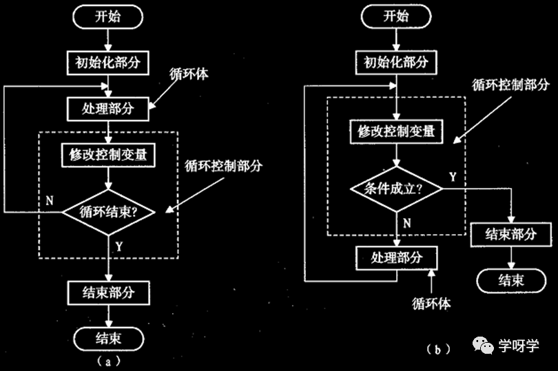
Loop programs generally consist of four main parts:

(1) Initialization: Prepares for the loop program, such as setting loop counts, and pre-setting values for variables and address pointers.

(2) Processing: The part of the program that is executed repeatedly, it is the entity of the loop program and the main part of the loop program.

(3) Loop control: This part modifies loop variables and control variables, and checks if the loop should end, until the end condition is met, at which point it exits the loop.

(4) End part: This part mainly analyzes, processes, and stores the results of the loop program.

4. Subroutines and Parameter Passing
(1) Concept of Subroutines
Usually, these basic operational functions are compiled into program segments as independent subroutines for repeated calls by different programs or the same program. A call instruction is placed where this operation is needed in the program, and when the program reaches the call instruction, it jumps to the subroutine to complete the specified operation and returns to continue executing the original program.
(2) Calling Subroutines
The instructions for calling subroutines are “ACALL” and “LCALL”. When executing the call instruction, the program address pointer PC is first changed (“ACALL” increases by 2, “LCALL” increases by 3), and then the PC value is pushed onto the stack, replaced by the new address value. When executing the return instruction, the PC value is popped back.
In subroutine calls, the main program should first store the relevant parameters in the agreed location, and the subroutine can retrieve parameters from the agreed location during execution. After the subroutine execution, the results are stored back in the agreed location, and when returning to the main program, the main program can retrieve the needed results from these agreed locations, which is the parameter passing.

Example: Convert a byte’s hexadecimal number in a certain internal RAM unit into two ASCII codes, storing the result in two consecutive internal RAM units.

Assuming a byte’s hexadecimal number is in internal RAM unit 40H, and the result is stored in units 50H and 51H, parameter passing can be done using the stack, and the program is as follows:

MAIN: MOV R1, #50H ; R1 is the pointer for storing results

MOV A, 40H ; Ais the hexadecimal number to be converted

SWAP A ; Convert the high half byte first

PUSH ACC ;Push onto the stack

LCALL HEASC ; Call the subroutine to convert the content of the low half byte to ASCII code;

Subroutine HEASC for conversion

POP ACC

MOV @R1, A ; Store the conversion result of the high half byte

INC R1

PUSH 40H

LCALL HEASC

POP ACC

MOV @R1, A ; Store the conversion result of the low half byte

END

HEASC: MOV R0, SP

DEC R0

DEC R0 ; R0 points to the address of the hexadecimal parameter

XCH A, @R0 ; Retrieve the parameter to be converted

ANL A, #0FH ; Retain the low half byte

ADD A, #2 ; Modify the A value

MOVC A, @A+PC ; Lookup table

XCH A,@R0; Return the result to the stack

RET

TAB: DB 30H, 31H, 32H, …

Introduction to Assembly Language Programming for Microcontrollers

Long press the image to follow

Discover more exciting content

WeChat ID: Mechanical-knowledge

Leave a Comment