Introduction
This article is a summary document I wrote after studying “Principles of Assembly Language”, Chapter 3 of “CSAPP”, and the “x86 data sheet”, as well as after a lot of Googling. It is intended for self-checking and review. I would be honored if it could be of assistance. If there are any errors or omissions, please do not hesitate to correct me.
1. From C to Assembly
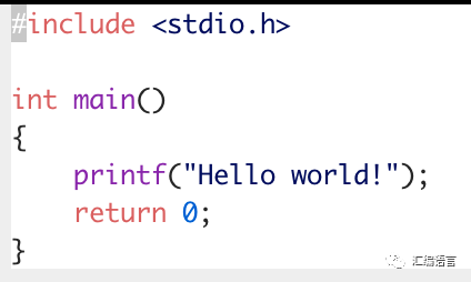
When we first learn C, we all write a file called hello.c, and by compiling (in a broad sense) this file (and the library files) and executing it, the computer will display the string “Hello world!” on the screen. However, we can’t help but wonder how the computer understands the code in hello.c.
Obviously, the computer cannot understand such abstract statements directly; it only recognizes high and low signals, which are binary languages (010010…). The compiler is responsible for “translating” the source files written by humans into binary files that the computer can understand. This “translation” involves a series of tools and complex processes, mainly removing/replacing macros in the source code by the preprocessor; the compiler translates the source code into assembly language (the main character here); the assembler translates the assembly code into object files, which are already binary files but still cannot be executed; the linker combines multiple object files into one executable file. Then, when we execute the executable file, the computer will move the binary code in the executable file to memory, disassemble it into a series of instructions, and the CPU executes these instructions in a certain order, thus completing the execution of the executable file. If this part is unclear, you need to remember one thing: the computer does not execute the source file directly, but executes the executable binary file generated after compilation.
Let me take hello.c under x86_64 as an example.
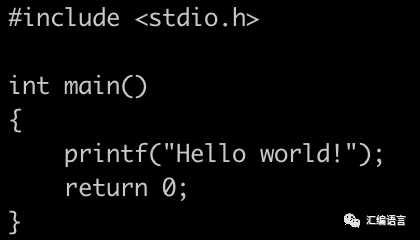
This is the source code
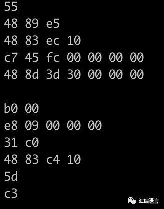
This is the binary code (displayed in hexadecimal for convenience)
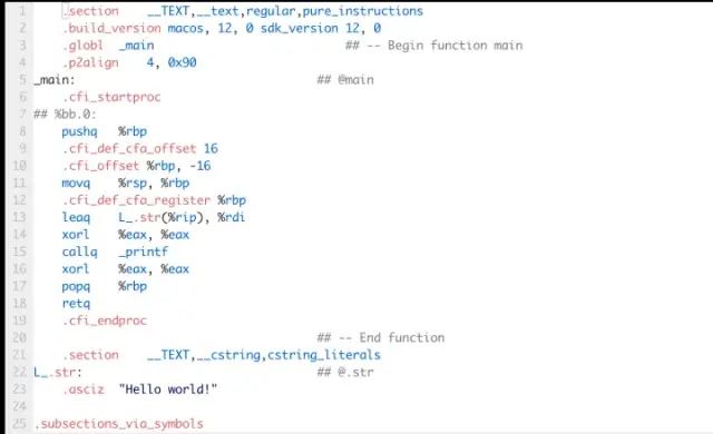
So what is assembly language? It is the bridge between source code and binary code, corresponding one-to-one with binary code while also being readable. It can be said that it is a textual representation of binary code. Before the invention of high-level languages, it was the programming language used by humans. Let’s take a look at what the assembly language corresponding to hello.c looks like.
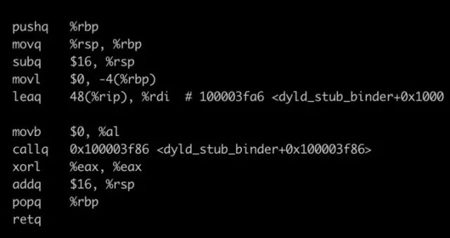
Assembly language (excerpt)
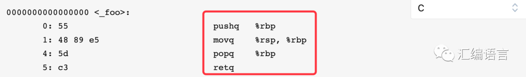
In fact, the one-to-one correspondence with binary code is easy to see:
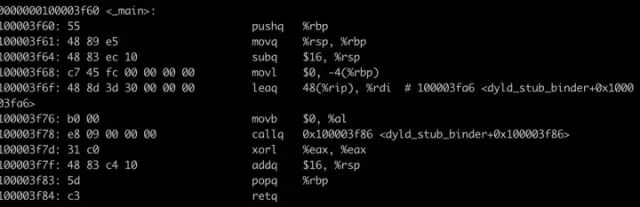
On the left is binary, and on the right is assembly
2. Assembly Language on x86_64 Platform
We know that high-level languages, such as C, are written independently of hardware platforms. The same C file can perform the same functions on x86, x86_64, and ARM (which can run on Windows, macOS, and Linux); this is one of the advantages of high-level languages. However, unfortunately, assembly language is highly customized, and the same source code generates different assembly code on different platforms. This is because assembly code is actually a series of instructions, but the instruction set architectures on different machines are different. On the x86_64 platform, you need to use its own complex instruction set; on ARM machines, you need to use its own reduced instruction set. To put it not very appropriately, you can think of generating executable binary files as building houses on x86_64 and ARM, where x86_64 only provides stones, and ARM only provides bricks. Although the final houses have the same functions, their appearances must be different.
I mainly use the x86_64 platform in my daily learning (as do most people), so this article addresses how to understand assembly language on x86_64. Speaking of which, I must mention some key points of the x86_64 platform.
2.1 16 64-bit Registers (And the Register File)
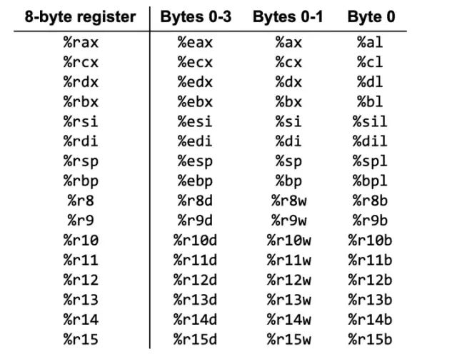
16 registers
The registers have different purposes, but they are mainly used to store the values of variables or addresses. Wait a minute, looking at this picture, isn’t there a confusion: there are clearly 16 registers, but why are there 64 names?
This is because the variables we encounter are not necessarily all 64 bits. For example, in the case of %rax, if I want to store a char type variable, I only need its low 8 bits, so it’s specially named %al (l stands for low); similarly, if I want to store a short type variable, I need its low 16 bits, so it’s named %ax; if the variable is of int type, I need the low 32 bits, named %eax.
Among these 16 registers, some have special tasks; for example, %rsp points to the top of the stack, %rax (and %eax, etc.) stores the return value of the function, and 6 registers are used to save the values of function parameters, while some have no restrictions.
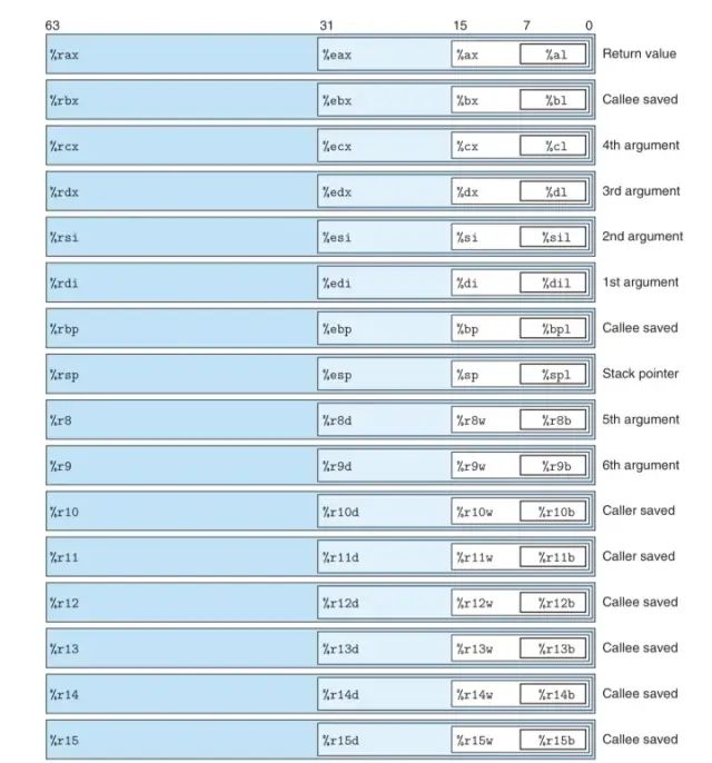
Other registers have caller-saved (caller saved) and callee-saved (callee saved) characteristics, which will be explained in detail later; here it is just a simple hint.
The following picture provides a more comprehensive view of the register heap and its characteristics (source: CSAPP):
2.2 (Virtual) Memory
Don’t worry about the word “virtual”; it is unrelated to the topic. Memory is like a warehouse, where both the binary code itself and some temporary variables are stored (some are also stored in the register file), and they are always ready for the CPU to use (access or write). You can think of memory as a super-large array, so each unit (byte) in memory has its own address.
2.3 Stack
If you have studied data structures, you will be very familiar with the characteristics of the stack: it follows the Last In First Out (LIFO) principle. There is also stack space in the x86-64 memory, which plays an important role during program execution: it stores temporary variables, serves as a transfer station for function calls, and saves return addresses (and possibly excessive) parameters, storing temporary variables for the current process.
The most important feature of the stack is the stack pointer, which is %rsp (one of the 16 registers). We know that the data that can be operated on the stack is only the data stored at the top of the stack, so almost all instructions related to the stack cannot do without this pointer. The stack has two operations: push and pop. In fact, pushing means moving the stack pointer down by a certain number of bytes, increasing the capacity of the stack, and then filling new data into the top of the stack. Why move down? Because the stack “grows” downwards, meaning that the address of the newly entered data is less than that of the old data. As shown in the figure below.
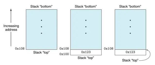
And popping means moving the stack pointer up by a certain number of bytes. There is no need to change the original top value of the stack, as the original top will be excluded from the stack’s range as the stack pointer moves up.
In function calls, the stack is divided into multiple parts, each dedicated to one process, called a “stack frame”, which will be discussed later.
2.4 PC Register
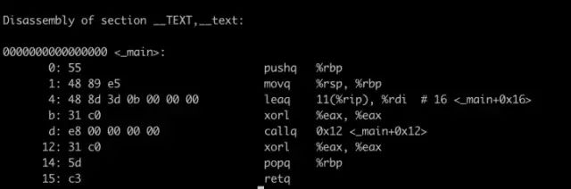
The PC (Program Counter) register, represented in assembly language as %rip, is a very critical register. It is the “conductor” when the CPU executes instructions. Since the instruction sequence is stored in memory, each instruction has a corresponding (virtual) address, as shown in the figure below:
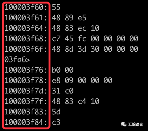
The red box contains the addresses corresponding to the instructions
The PC register stores the address of the next instruction to be executed. Therefore, after executing an instruction, the address of the next instruction is placed in the PC register. Figuratively speaking, the PC register is like a general pointing where to hit. If you don’t want to execute instructions one by one in spatial order, you just need to move the address of the instruction you want to execute into the PC register (in fact, jump instructions and function calls are implemented using this principle).
The PC register does not explicitly appear in the assembly code; its value changes secretly.
2.5 Condition Codes
Besides the PC register, there is also something called “condition codes” lurking in the shadows. Its function is to record the status after the last arithmetic or logical instruction. This will be explained in detail later.
3 Instructions
As mentioned earlier, assembly code is a sequence of many instructions, and one instruction can complete one CPU operation. So let’s study the characteristics and format of a single instruction in detail.
One instruction consists of an opcode and 0 to 2 operands. The opcode specifies the operation to be performed by the current instruction, such as adding two numbers, and the operands are the objects of the opcode’s action. Therefore, the length of the instruction is not fixed, ranging from 1 byte to 15 bytes.
3.1 Operands
Operands can be immediate values, registers, or memory addresses. Below are the representations of these three types of operands (from the x64 data sheet):
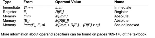
Please read carefully
For example, $5 is an immediate value, its value is 5; %rax is a register, its value is the value in register %rax; 0xf7 is a memory address, its value is a certain type of value at memory address 0x07; (%rax) is also a memory address, except that this address is stored in register %rax; 0xf7(%rax, %rbp, 4) is also a memory address, and all memory addressing methods can be written in this format.
3.2 Opcodes
Opcodes can be classified into arithmetic logic type, data transfer type, control type, etc.
Arithmetic and logic instruction opcodes
See the following instruction
addq $3, %rdi
add represents addition, the first operand is the source operand, and the second is the destination operand. This instruction adds the immediate value 3 to the register %rdi. If the value stored in %rdi was 8 before, it becomes 11 after executing this instruction.
So what does the suffix q represent? It indicates the size of the operand. There are 4 types of suffixes:
b – byte (8 bits),
w – word (16 bits),
l – double word (32 bits)
q – quad word (64 bits)
In addition to addition, arithmetic logic types also include subtraction, multiplication, XOR, bitwise OR, bitwise AND, etc. The table below:
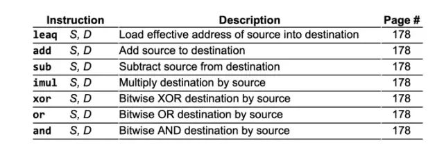
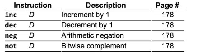
All the examples above have two operands; in fact, there are also arithmetic logic operations with only one operand:
2. Data transfer instruction opcodes:
movb $bl, %al
Indicates assigning the value in register %bl to %al
pushq %rbp
Indicates pushing the value of %rbp onto the stack: first reducing the value of the stack top pointer register %rsp by 8, and then assigning the value of %rbp to the memory unit pointed to by %rsp. (Recall the previous discussion on pushing)
popq %rsi
Indicates popping the value of 8 bytes from the top of the stack and assigning it to register %rsi.
3. Control types
4. Comparison and testing opcodes
cmpb %al, %bl
testq %rax, %rbx
4 Practical Application
Next, I will present a series of examples from simple to complex to illustrate how to understand assembly code.
First, how to obtain a segment of assembly code? There are two methods.
First prepare a source file (I use hello.c)
Then use the command
gcc -Og -S hello.c
Replace hello.c with your file name, and you will get a *.s file, which contains the assembly code corresponding to this source code:
Note that adding -Og makes the generated assembly code correspond as closely as possible to the source code; otherwise, compiler optimizations will make it difficult to see the relationship between the assembly code and the source code.
However, the assembly code obtained this way is not concise and neat enough. We will use the method below to obtain the assembly code:
First compile the source code to get the object file hello.o:
gcc -c -Og hello.c
Then use the disassembly command:
objdump -d hello.o
The assembly code will be displayed.
It is neater than the previous code.
Now let’s officially start the practical application.
Example 1
Let’s start with the simplest code:
void foo() { return; }
A function that does nothing, with no parameters and no return value. Let’s see what its assembly code looks like:
0000000000000000 <_foo>: 0: 55 pushq %rbp 1: 48 89 e5 movq %rsp, %rbp 4: 5d popq %rbp 5: c3 retq
First, look at the first line:
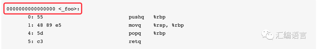
This line is divided into two parts; the first part is 16 zeros. Note that this zero is not just a simple zero; it is hexadecimal 0, so these zeros are actually 64 zeros. And the system is 64-bit… so you can guess, it is the virtual address of this function. The second part is <_foo>, and _foo is the function name, which is used as a marker for this function. When other functions want to call this function, they need to use the function name. The assembly function name is generated by adding a “_” prefix to the original function name.
The following is the function body. Obviously, it consists of 4 instructions.
Let’s first look at the first column:
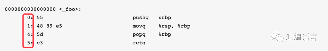
This is the address of each instruction, which is also in hexadecimal. Since the second instruction has 3 bytes (48 89 e5), the address of the third instruction differs by 3 from the second instruction.
And after the address, the machine code of the instruction is displayed:
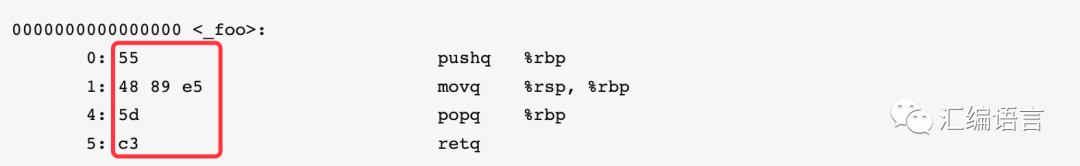
After that, the assembly code is shown:
Let’s analyze these four lines of assembly code one by one:
First line of code:
pushq %rbp
From previous discussions, we already know that this line pushes the value of %rbp onto the stack. Why do this? Because registers have the rules of “caller saved” and “callee saved”. Let me explain in detail.
Among the 16 registers, except for %rsp, which stores the stack pointer, generally speaking, the remaining 15 can be used to store variables. However, when it comes to function calls, some of the registers’ functions are limited: %rax will be used to store return values; %rdi, %rsi, %rdx, %rcx, %r8, %r9 are six registers that will be used to save parameters; the remaining 8 can still store any values. But the problem is that there is only one set of registers, and now two functions (the caller and the callee) need to use them, which will inevitably cause conflicts. So what to do? The answer is to save the values of these registers on the stack before the callee uses them, and after the callee finishes using them, restore the values saved in the stack back to the registers. Based on who is responsible for saving these registers, they can be divided into two categories: “caller saved” and “callee saved”. “Caller saved”: that is, before calling the callee, the caller pushes the registers used; “callee saved”: that is, the callee pushes the registers it will use. Below is a summary of which are caller saved and which are callee saved registers.
|
Caller Saved Registers |
Callee Saved Registers |
|
%r10, %r11 |
%rbx, %rbp, %r12-15 |
Returning to this line of code, it is evident that we push %rbp onto the stack because the second line of code changes the value of %rbp, and %rbp is a callee saved register.
2. Second line of code
movq %rsp, %rbp
This line of code assigns the value of %rsp to %rbp. This line seems somewhat redundant here (but we will see its role in later examples); its purpose is to make %rbp the base pointer, and the addresses of subsequent function (more than 6) parameters, intermediate variables, etc. will be saved as offsets from the address pointed to by %rbp.
3. Third line of code
popq %rbp
Pop the data from the top of the stack and assign it to %rbp. This corresponds to pushq %rbp and is intended to restore the previous value of %rbp.
4. Fourth line of code
retq
The callee finishes executing and returns to the caller.
Example 2
We will add a return value based on Example 1.
int foo() { return 0; }
The corresponding assembly code generated:
0000000000000000 <_foo>: 0: 55 pushq %rbp 1: 48 89 e5 movq %rsp, %rbp 4: 31 c0 xorl %eax, %eax 6: 5d popq %rbp 7: c3 retq
We see that the only difference from Example 1 is the addition of this line.
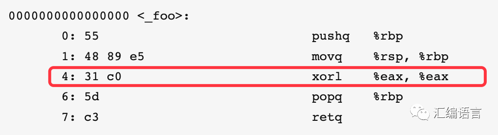
This line performs a bitwise XOR on %eax with itself, resulting in %eax becoming 0 (and it is of int type). And %eax happens to be the register that stores the return value.
Example 3
We will add two parameters based on Example 2:
int foo(int a, int b) { return a + b; }
The generated assembly code:
0000000000000000 <_foo>: 0: 55 pushq %rbp 1: 48 89 e5 movq %rsp, %rbp 4: 8d 04 37 leal (%rdi, %rsi), %eax 7: 5d popq %rbp 8: c3 retq
Note this line:
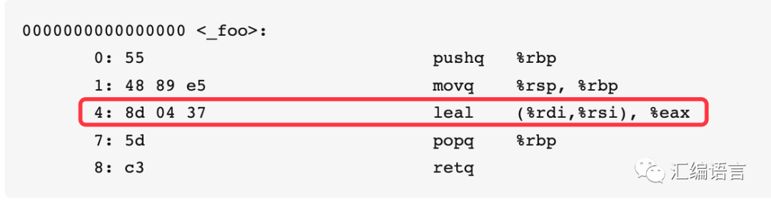
In the source code, adding the two parameters and returning is compiled into this line of assembly code. First, let’s look at what leal does: it adds the values in %rdi and %rsi and assigns the result to %eax. In Example 1, it has already been explained that %rdi and %rsi store the first and second parameters, respectively, and %eax stores the return variable. So this line of code perfectly corresponds to the source code.
However… wait, have you noticed a problem: there are only 6 registers used for passing parameters, but what if there are 7 or more parameters?
Example 4
Change the parameters to 8.
int foo(int a1, int a2, int a3, int a4, int a5, int a6, int a7, int a8) { return a1 + a2 + a3 + a4 + a5 + a6 + a7 + a8; }
This is its assembly code:0000000000000000 <_foo>: 0: 55 pushq %rbp 1: 48 89 e5 movq %rsp, %rbp 4: 8d 04 37 leal (%rdi, %rsi), %eax 7: 01 d0 addl %edx, %eax 9: 01 c8 addl %ecx, %eax b: 44 01 c0 addl %r8d, %eax e: 44 01 c8 addl %r9d, %eax 11: 03 45 10 addl 16(%rbp), %eax 14: 03 45 18 addl 24(%rbp), %eax 17: 5d popq %rbp 18: c3 retq
Please see the code in the red box below:
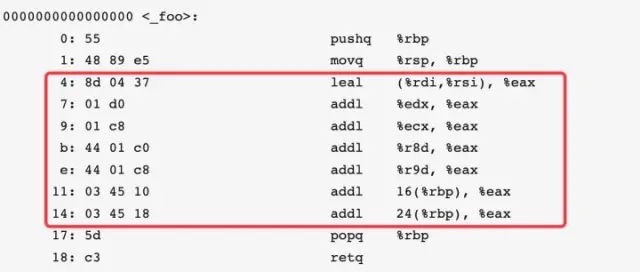
The 6 parameter passing registers %rdi, %rsi, %rdx, %rcx, %r8d, %r9d appear in order, which verifies that indeed the first 6 parameters are stored in these registers. The last two lines in the red box add the doubleword data stored at 16(%rbp) and 24(%rbp) to %eax, indicating that the 7th and 8th parameters are stored in these two places. It seems that if there are more than 6 parameters, the extra parameters will be stored in the stack for passing.
But why are %rbp’s offsets 16 and 24 bytes? To clarify why the 7th and 8th parameters are stored at this location, let’s conduct the next experiment.
Example 5
Add the caller function caller, and to match (sorry, I have OCD), rename the function foo to callee.
int callee(int a1, int a2, int a3, int a4, int a5, int a6, int a7, int a8) { return a1 + a2 + a3 + a4 + a5 + a6 + a7 + a8; } int caller() { return callee(1, 2, 3, 4, 5, 6, 7, 8) + 9; }
Its assembly code is:0000000000000000 <_callee>: 0: 55 pushq %rbp 1: 48 89 e5 movq %rsp, %rbp 4: 8d 04 37 leal (%rdi, %rsi), %eax 7: 01 d0 addl %edx, %eax 9: 01 c8 addl %ecx, %eax b: 44 01 c0 addl %r8d, %eax e: 44 01 c8 addl %r9d, %eax 11: 03 45 10 addl 16(%rbp), %eax 14: 03 45 18 addl 24(%rbp), %eax 17: 5d popq %rbp 18: c3 retq 19: 0f 1f 80 00 00 00 00 nopl (%rax)
0000000000000020 <_caller>: 20: 55 pushq %rbp 21: 48 89 e5 movq %rsp, %rbp 24: bf 01 00 00 00 movl $1, %edi 29: be 02 00 00 00 movl $2, %esi 2e: ba 03 00 00 00 movl $3, %edx 33: b9 04 00 00 00 movl $4, %ecx 38: 41 b8 05 00 00 00 movl $5, %r8d 3e: 41 b9 06 00 00 00 movl $6, %r9d 44: 6a 08 pushq $8 46: 6a 07 pushq $7 48: e8 00 00 00 00 callq 0x4d <_caller+0x2d> 4d: 48 83 c4 10 addq $16, %rsp 51: 83 c0 09 addl $9, %eax 54: 5d popq %rbp 55: c3 retq
We find that the code sequentially loads immediate numbers $1 to $6 into the corresponding registers, which is fine. Then, it pushes $8 and $7 onto the stack one after the other, and during this process, %rsp implicitly decreases by 8 + 8 = 16 bytes (because it needs 8 bytes to store a quadword). From here we can see that the extra parameters are pushed onto the stack in reverse order. So in Example 4, 16(%rbp) stores $7, and 24(%rbp) stores $8.
Next, let’s look at the call command:
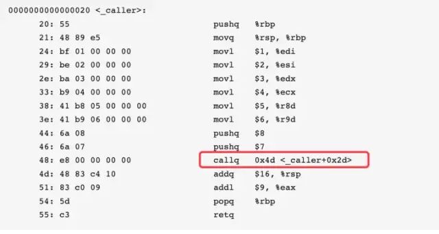
We all know that this instruction calls the callee function, but the operand after callq 0x4d <_caller+0x2d> is not the address of callee, because the program I showed is unlinked, and callq does not know the address of callee. After linking, the assembly code is as follows:
0000000100003f60 <_callee>:100003f60: 55                            pushq  %rbp100003f61: 48 89 e5                      movq  %rsp, %rbp100003f64: 8d 04 37                      leal  (%rdi, %rsi), %eax100003f67: 01 d0                         addl  %edx, %eax100003f69: 01 c8                         addl  %ecx, %eax100003f6b: 44 01 c0                      addl  %r8d, %eax100003f6e: 44 01 c8                      addl  %r9d, %eax100003f71: 03 45 10                      addl  16(%rbp), %eax100003f74: 03 45 18                      addl  24(%rbp), %eax100003f77: 5d                            popq  %rbp100003f78: c3                            retq100003f79: 0f 1f 80 00 00 00 00          nopl  (%rax)
0000000100003f80 <_main>:100003f80: 55                            pushq  %rbp100003f81: 48 89 e5                      movq  %rsp, %rbp100003f84: bf 01 00 00 00                movl  $1, %edi100003f89: be 02 00 00 00                movl  $2, %esi100003f8e: ba 03 00 00 00                movl  $3, %edx100003f93: b9 04 00 00 00                movl  $4, %ecx100003f98: 41 b8 05 00 00 00             movl  $5, %r8d100003f9e: 41 b9 06 00 00 00             movl  $6, %r9d100003fa4: 6a 08                         pushq  $8100003fa6: 6a 07                         pushq  $7100003fa8: e8 b3 ff ff ff                callq  0x100003f60 <_callee>100003fad: 48 83 c4 10                   addq  $16, %rsp100003fb1: 83 c0 09                      addl  $9, %eax100003fb4: 5d                            popq  %rbp100003fb5: c3                            retq
Notice that the operand after callq 0x100003f60 <_callee> is indeed the address of callee.
In any case, we have determined that this line of instruction is calling the callee function, and this process implicitly occurs as follows:
Push the “return address” onto the stack. The so-called return address is the address of the next instruction after the call instruction, which in this case (after linking) is 0x100003fad. The purpose of pushing the return address onto the stack is to allow the callee to continue executing the next instruction after it finishes executing. Again, remember that pushing means %rsp will decrease by 8 bytes.
Set the PC register to the address of the called function, which is 0x100003f60 here. As mentioned earlier, the PC register is the conductor, pointing to which instruction the CPU will execute next. So after executing the callq instruction, the next step will begin executing the instructions of callee.
Do you remember our question? Why do the 7th and 8th parameters have an offset of 16 bytes from %rbp? The 8th parameter has an offset of 24 bytes from %rbp. This is because the address of the 7th parameter is separated from %rbp by the “return address” and the “old value of %rbp”, a total of 16 bytes, while the 8th parameter is separated by this 16 bytes plus 8 bytes for the parameter itself.
Having laid this groundwork, it’s time to show this diagram (from CSAPP)!
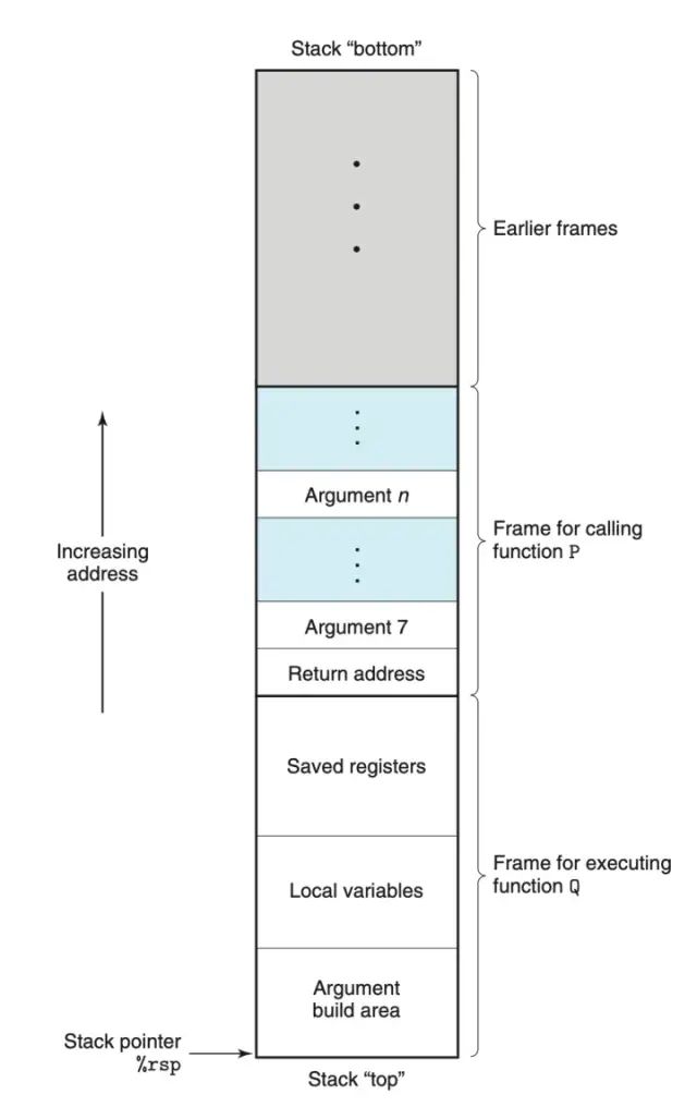
Structure of the Stack Frame
Now let’s interpret this diagram. The function P is a caller function, while function Q is a callee.
As we mentioned earlier, during the execution of the program, the stack is divided into multiple “stack frames”, as shown in the diagram above. Different processes have their own corresponding stack frames, and the stack frame of the currently executing process is at the top of the stack.
The stack frame is the area for passing parameters, storing return information, registers, and local variables during function calls. I believe through the previous examples, we have seen the power of the stack frame. Here, we will summarize the entire process of function calling, marking the parts involving the stack frame in bold:
In the caller, the required parameters are saved in 6 registers; if there are more than 6 parameters, the extra parameters are pushed onto the stack in reverse order, and note that the size of the parameters must be a multiple of 8.
The return address is pushed onto the stack
The address of the callee is passed to the PC register %rip
The callee’s saved registers are pushed onto the stack
Memory space is allocated for local variables
The instructions of the callee are executed
The return value is stored in %rax
The value of %rsp is increased to destroy the current stack frame
The retq instruction is executed. This instruction assigns the return address to the PC register
PS: If the return value cannot be stored in a register, it will also be stored in the stack frame.
The structure of the stack frame shown in the diagram is generally applicable, but in many cases, some units are not necessary. For example, in Examples 1-3, since the function parameters do not exceed 6, there is no need to allocate memory to store the 7th to nth parameters.
For instance, the Local variables area is used to store temporary variables, but some functions do not require temporary variables.
Now that you’ve seen this, let’s take a break. We’ll start the next example soon, beginning with simple examples.
Excerpted from https://zhuanlan.zhihu.com/p/469950256