
Click on the top“Baijia Technology”,to pin the public account
Embedded essentials delivered promptly
——

Author: Ruan Yifeng Link: http://www.ruanyifeng.com/blog/2018/01/
Learning programming is essentially learning high-level languages, which are designed for humans.
However, computers do not understand high-level languages; they must be compiled into binary code to run. Learning high-level languages does not equate to understanding the actual execution steps of the computer.
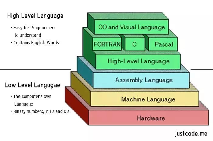
The only language that computers truly understand is low-level language, which is specifically used to control hardware. Assembly language is a low-level language that directly describes/controls the CPU’s operations. If you want to know what the CPU is actually doing and how code executes, you must learn assembly language.
Assembly language is not easy to learn, and even concise introductions are hard to find. Here, I will attempt to write the most understandable assembly language tutorial to explain how the CPU executes code.

We know that the CPU is responsible only for computation and lacks intelligence. You input an instruction, and it executes once, then stops, waiting for the next instruction.
These instructions are in binary, known as opcodes (operation codes); for example, the addition instruction is 00000011. The compiler’s role is to translate the program written in high-level language into a series of opcodes.
For humans, binary programs are difficult to read, and it is hard to discern what the machine is doing through the code. To address readability issues and occasional editing needs, assembly language was born.
Assembly language is a textual form of binary instructions, corresponding one-to-one with binary instructions. For example, the addition instruction 00000011 is written in assembly language as ADD. Once converted back to binary, assembly language can be directly executed by the CPU, making it the lowest-level low-level language.
In the early days, programming was done by hand-writing binary instructions and inputting them into the computer via various switches. For instance, to perform addition, one would press the addition switch. Later, paper tape punch machines were invented to input binary instructions automatically by punching holes in the tape.
To solve the readability issue of binary instructions, engineers wrote those instructions in octal. Converting binary to octal is straightforward, but octal is also not very readable. Naturally, it ended up being expressed in text, with the addition instruction written as ADD. Memory addresses were no longer directly referenced but were represented with labels.
This added an extra step, where these textual instructions had to be translated into binary; this step is called assembling, and the program that completes this step is called an assembler. The text it processes is naturally called assembly code. After standardization, it was referred to as assembly language, abbreviated as asm, translated into Chinese as 汇编语言.
Each CPU’s machine instructions are different, so the corresponding assembly language is also different. This article introduces the most common x86 assembly language, which is used by Intel’s CPUs.
To learn assembly language, you must first understand two concepts: registers and memory models.
First, let’s look at registers. The CPU is responsible for calculations but does not store data. Data is generally stored in memory, and when the CPU needs it, it reads from and writes to memory. However, the CPU’s calculation speed is much faster than the speed of reading and writing to memory. To avoid being slowed down, the CPU has its own level 1 and level 2 caches. Essentially, CPU caches can be considered as faster memory.
However, CPU caches are still not fast enough, and the addresses of data in the cache are not fixed; each read and write requires addressing, which can also slow down performance. Therefore, in addition to caches, the CPU also has registers to store the most frequently used data. This means that the most frequently read and written data (like loop variables) will be placed in registers, allowing the CPU to prioritize reading and writing registers before exchanging data with memory.
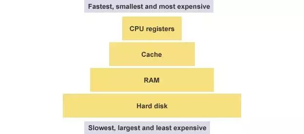
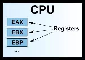
Registers do not distinguish data by addresses but by names. Each register has its own name, and we tell the CPU which specific register to retrieve data from, making this the fastest method. Some compare registers to the CPU’s zero-level cache.
Early x86 CPUs had only eight registers, each with different purposes. Now, there are over 100 registers, all becoming general-purpose registers without specific assignments, but the names of the early registers have been retained.
EAX
EBX
ECX
EDX
EDI
ESI
EBP
ESP
Among these eight registers, the first seven are general-purpose. The ESP register has a specific purpose: it stores the address of the current stack.
We often see names like 32-bit CPU and 64-bit CPU, which actually refer to the size of the registers. A 32-bit CPU has register sizes of 4 bytes.
Registers can only hold a small amount of data; most of the time, the CPU needs to instruct registers to exchange data directly with memory. Therefore, in addition to registers, it is essential to understand how memory stores data.
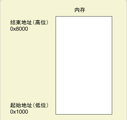
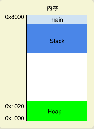
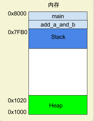
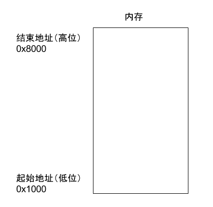
When a program runs, the operating system allocates a segment of memory to store the program and the data generated during execution. This memory has a starting and an ending address, such as from 0x1000 to 0x8000, where the starting address is the smaller one, and the ending address is the larger one.
During program execution, for dynamic memory allocation requests (like creating new objects or using the malloc command), the system will allocate a portion of the pre-allocated memory to the user, following specific rules starting from the starting address (in reality, the starting address will have some static data, which is ignored here). For example, if a user requests 10 bytes of memory, it will be allocated starting from address 0x1000, up to address 0x100A. If another request for 22 bytes is made, it will be allocated up to 0x1020.
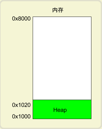
This memory area allocated due to a user’s request is called the Heap. It grows from the starting address upwards (address-wise). An important feature of the Heap is that it does not disappear automatically; it must be manually released or reclaimed by a garbage collection mechanism.
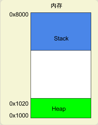
Aside from the Heap, other memory allocations are called the Stack. In simple terms, the Stack is the memory area temporarily occupied during function execution.
See the example below.
int main() {
   int a = 2;
   int b = 3;
}
In the above code, when the system starts executing the main function, it will create a frame in memory for it, where all internal variables of main (like a and b) are stored. After the main function finishes executing, this frame will be reclaimed, releasing all internal variables and no longer occupying space.
If a function calls another function, what happens?
int main() {
   int a = 2;
   int b = 3;
   return add_a_and_b(a, b);
}
In the above code, the main function calls the add_a_and_b function. When executing this line, the system will also create a new frame for add_a_and_b to store its internal variables. This means that at this time, two frames exist simultaneously: main and add_a_and_b. Generally, the number of frames corresponds to the number of layers in the call stack.
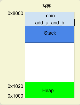
Once add_a_and_b finishes executing, its frame will be reclaimed, and the system will return to where the main function was interrupted and continue executing. This mechanism allows for layered function calls, with each layer able to use its local variables.
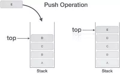
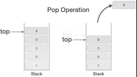
All frames are stored in the Stack. Since frames are stacked on top of each other, the Stack is called a stack. Creating a new frame is called “pushing onto the stack”; the English term is push. Reclaiming the stack is called “popping from the stack”; the English term is pop. The Stack’s characteristic is that the last frame pushed is the first to pop (because the innermost function call ends first), which is called a “last in, first out” data structure. Each time a function execution ends, a frame is automatically released; when all functions finish executing, the entire Stack is released.
The Stack is allocated from the end address of the memory area, from high addresses to low addresses. For example, if the end address of the memory area is 0x8000, and the first frame is assumed to be 16 bytes, the next allocation will start from 0x7FF0; if the second frame requires 64 bytes, the address will move to 0x7FB0.
An ExampleAfter understanding registers and memory models, we can see what assembly language is. Below is a simple program example.c.
int add_a_and_b(int a, int b) {
   return a + b;
}
int main() {
   return add_a_and_b(2, 3);
}
GCC will convert this program into assembly language.
$ gcc -S example.c
After executing the command above, a text file example.s will be generated, containing assembly language with dozens of lines of instructions. To put it simply, a simple operation in a high-level language may consist of several, or even dozens, of CPU instructions. The CPU executes these instructions sequentially to complete this operation.
The simplified version of example.s looks something like this.
_add_a_and_b:
   push   %ebx
   mov    %eax, [%esp+8]
   mov    %ebx, [%esp+12]
   add    %eax, %ebx
   pop    %ebx
   ret

_main:
   push   3
   push   2
   call   _add_a_and_b
   add    %esp, 8
   ret
As you can see, the two functions in the original program, add_a_and_b and main, correspond to the two labels _add_a_and_b and _main. Each label contains the CPU execution flow for that function.
Each line is an operation executed by the CPU. It can be divided into two parts, taking one line as an example.
push %ebx
This line contains push as the CPU instruction, and %ebx as the operand used by this instruction. A CPU instruction can have zero to multiple operands.
Now, I will explain this assembly program line by line. I recommend readers to copy this program into another window to avoid scrolling back up while reading.
Push Instruction
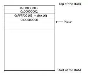
According to convention, the program starts executing from the _main label, at which point a frame will be created on the Stack for main, and the address pointed to by the Stack will be written into the ESP register. If data needs to be written into this frame later, it will be written at the address stored in the ESP register.
Then, the first line of code begins execution.
push 3
The push instruction is used to place operands onto the Stack, here writing 3 into the main frame.
Although it seems simple, the push instruction actually has a preceding operation. It first retrieves the address in the ESP register, subtracts 4 bytes from it, and then writes the new address into the ESP register. The subtraction is because the Stack grows from high to low addresses, and 4 bytes is because the type of 3 is int, which occupies 4 bytes. After obtaining the new address, 3 will be written into the first four bytes of this address.
push 2
The second line is similar; the push instruction writes 2 into the main frame, positioned right next to the previously written 3. At this time, the ESP register will again subtract 4 bytes (cumulatively subtracting 8).
Call Instruction
The third line’s call instruction is used to invoke a function.
call _add_a_and_b
The code above indicates calling the add_a_and_b function. At this point, the program will look for the _add_a_and_b label and create a new frame for that function.
It will then begin executing the code of _add_a_and_b.
push %ebx
This line indicates that the value in the EBX register is written into the _add_a_and_b frame. This is because the register will be used later, so its value is retrieved first and will be written back after it is used.
At this point, the push instruction will again subtract 4 bytes from the address in the ESP register (cumulatively subtracting 12).
Mov Instruction
The mov instruction is used to write a value into a register.
mov %eax, [%esp+8]
This line of code indicates that the address in the ESP register is incremented by 8 bytes to get a new address, and data will be retrieved from the Stack at this address. Based on previous steps, it can be deduced that the value retrieved here is 2, which will be written into the EAX register.
The next line of code does the same thing.
mov %ebx, [%esp+12]
The code above retrieves data from the Stack at the address incremented by 12 bytes in the ESP register, this time retrieving 3 and writing it into the EBX register.
Add Instruction
The add instruction is used to add two operands and write the result into the first operand.
add %eax, %ebx
The code above adds the value in the EAX register (which is 2) to the value in the EBX register (which is 3), resulting in 5, and writes this result into the first operand, the EAX register.
Pop Instruction
The pop instruction is used to retrieve the most recently written value from the Stack (i.e., the value at the lowest address) and write this value to the specified operand.
pop %ebx
The code above indicates that the most recently written value from the Stack (i.e., the original value of the EBX register) is retrieved and written back into the EBX register (since the addition is complete, the EBX register is no longer needed).
Note that the pop instruction will also increment the address in the ESP register by 4, which reclaims 4 bytes.
Ret Instruction
The ret instruction is used to terminate the current function’s execution and return control to the upper function. In other words, the current function’s frame will be reclaimed.ret can be observed that this instruction has no operands.
As the add_a_and_b function terminates, the system returns to the place where the main function was interrupted, continuing execution.
add %esp, 8
The code above indicates that the address in the ESP register is manually incremented by 8 bytes and written back to the ESP register. This is because the address in the ESP register points to the start of the Stack, and the previous pop operation has reclaimed 4 bytes; here, another 8 bytes are reclaimed, equaling a complete reclaim.
ret
Finally, when the main function ends, the ret instruction exits the program execution.
-THE END-
Previous article:Pointers and Memory Leaks in C Language
Promotion
To ensure code simplicity, Linux kernel versions above 3.x all support device trees (dts),
it can be said that device trees are the trend, and learning about device trees is essential.Mastering device tree knowledge is one of the essential skills for driver engineers.
However, beginners in device trees often encounter the following issues:
-
Various tutorials online are inconsistent and based on different kernel versions. Following them exactly will inevitably lead to various strange problems, sometimes taking a long time to resolve, causing anxiety and wasting time.
-
Device trees use many nodes and properties. Beginners often find it hard to understand. Without detailed guidance and pointers, learning becomes extremely difficult.
-
If you look closely, you will find that there is no complete and detailed video on device trees online; they are either not detailed enough or only touch on key parts.
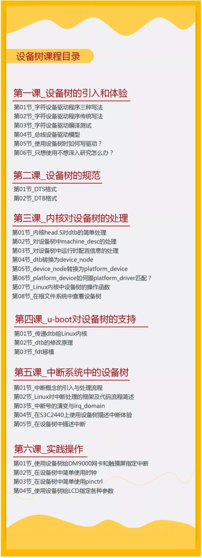
Thus, Baijia Network has launched a video course titled “Detailed Explanation of Linux Device Trees”. In this course, we will use Linux 4.19 as the foundation, and the instructor will combine their experience and summaries from work to help you understand the use of device trees, avoiding various issues caused by version mismatches when learning from scattered tutorials online, optimizing the learning experience and enhancing learning efficiency.
Who is the instructor?
Wei Dongshan, Technical Director of Shenzhen Baijia Network Technology Co., Ltd.,
Graduated from the University of Science and Technology of China with dual degrees in physics and software,
15 years of experience in embedded frontline programming and development.
Author of the bestselling Linux-related book <<Complete Manual for Embedded Linux Application Development>>.
Long-term engagement in embedded teaching, with a deep understanding of the pain points of embedded beginners, and able to explain them in an easy-to-understand manner. Over the past ten years, they have tirelessly nurtured thousands of outstanding embedded engineers.
For the past ten years, the rights and interests of students have always been prioritized..
Grounded in after-sales service and Q&A, they are a leader in the field of online training for embedded Linux/Android.
If you are a beginner in device trees, or an embedded engineer who needs to use device trees in your work, this course is tailored for you. We are confident that after completing the course, you will not only be able to modify device trees and understand device tree files but also gain a deeper understanding of the internal principles of device trees.
Why are we so confident?
-
First, we will explain the differences between non-device tree code and code that uses device trees, allowing you to understand the role of device trees more profoundly.
-
We will explain while drawing and writing code on-site, first theory then practice, focusing on difficult points (like how the kernel handles device trees).
-
Wiki tutorials, in-class notes, and code will be comprehensive, assisting comprehension while learning, filling knowledge gaps to find your learning path.
After completing the course, you will gain:
-
A profound understanding of the origin and role of device trees
-
The ability to understand device tree files and modify drivers to support device trees
-
A better understanding of the internal principles of device trees
Course Directory
Purchase link:
https://item.taobao.com/item.htm?spm=a1z10.1-c-s.w5003-18996326770.1.764a82accZHBAf&id=577749510933&scene=taobao_shop
If you have concerns, please try first:
Traditional method of writing character device drivers▲
What if I just want to use device trees without delving deeper? ▲
Below are some evaluations from device tree students ▼
How to get the selected dry goods articles from this public account?
Please reply “m” in the public account backend to get it.
Join the community
The official WeChat group of Wei Dongshan is open for students to communicate. Add the administrator’s WeChat (13266630429, verification: join group) to join. Limited spots are available on a first-come, first-served basis.

If you like it, please click [Like]