Click the image above to follow “Chuangxue Electronics” for easy access to electronic knowledge.
The interrupt system of the 80C51 has 5 interrupt sources (the 8052 has 6), with 2 priority levels, allowing for dual-level interrupt nesting.
The structure of the interrupt system in the MCS-51 series microcontroller is as follows:
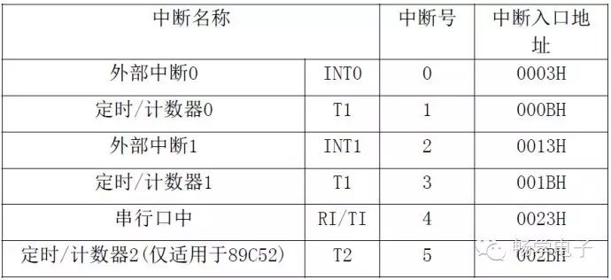
Special registers related to the interrupt system:
1) Interrupt Enable Register (IE) —— Controls the enabling and masking of each interrupt.
2) Interrupt Priority Register (IP) —— Sets the priority of each interrupt.
3) Timer/Counter Control Register (TCON) —- Controls timers and external interrupts.
4) Serial Port Control Register (SCON) —— Controls serial interrupts.
There are three types of interrupts:
1) T0 and T1 are two timer/counter interrupts provided by the internal timer;
2) INT0 and INT1 are two external interrupts provided by pins P3.2 and P3.3;
3) RX and TX are used for serial port interrupts provided by the internal serial port.
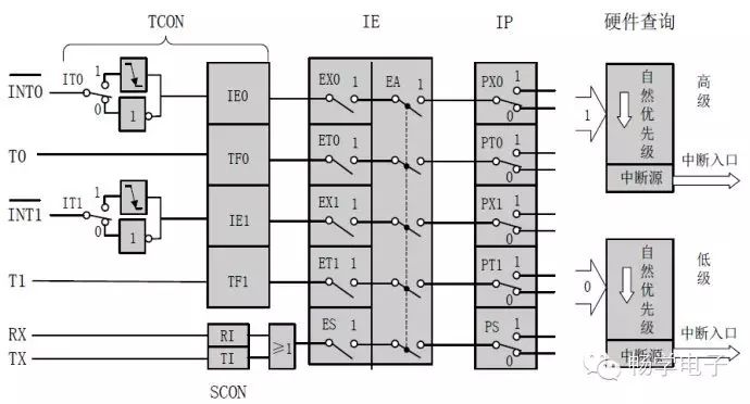
1. (P3.2)/(P3.3) can be selected to be active low or falling edge sensitive by IT0(TCON.0)/IT1(TCON.2). When the CPU detects a valid interrupt signal on the P3.2/P3.3 pins, the interrupt flag IE0(TCON.1)/IE1(TCON.3) is set to 1, requesting an interrupt from the CPU.
3. TF0(TCON.5)/TF1(TCON.7) are the overflow interrupt request flags for the internal timer/counter T0/T1. When the timer/counter T0/T1 overflows, TF0/TF1 is set, requesting an interrupt from the CPU.
5. RI(SCON.0) or TI(SCON.1) are the serial port interrupt request flags. RI is set when a frame of serial data is received, or TI is set when a frame of serial data is sent, requesting an interrupt from the CPU.
The above only requests an interrupt from the CPU. To receive a response from the CPU, the corresponding interrupt enable IE and priority IP must also be set, so that the interrupt can be responded to.
1) Using Timer Interrupts (using Timer 0 as an example)
……
TMOD |= 0x01 | 0x04; // Use mode 1, 16-bit counter; using the ‘|’ symbol allows multiple timers to be used without interference.
TH0=0xFF; // Set initial value
TL0=245; // Count from 245 to 255
EA=1; // Enable global interrupts
ET0=1; // Enable timer interrupts
TR0=1; // Turn on the timer
void Timer0_isr(void) interrupt 1 using 1 // Interrupt Service Routine
{
TH0=0xFF; // Reset initial value
TL0=245;
……
}
2) Using External Interrupts (using External Interrupt 0 as an example)
…………
EA=1; // Enable global interrupts
EX0=1; // Enable external interrupt 0
IT0=0; // Level trigger
void ISR_Key(void) interrupt 0 using 1 // Interrupt Service Routine
{
…………
> > > > > > > > > > > > > > > > > > > > > > > > > > > > > > > > > > > > > > > > > > > > > > > > > > > > > >
==> Go to www.eeskill.com to learn more!