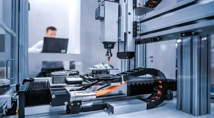
Integration of PLC and Industrial Robots: Automation Solutions for Assembly Lines
In modern industrial automation production, the integration of PLC (Programmable Logic Controller) and industrial robots has become an important means to enhance production efficiency and quality. Today, we will introduce how to utilize PLC and industrial robots to achieve automated control of assembly lines from a beginner’s perspective, helping you quickly get started and understand the key technologies involved.
1. Basic Concepts of PLC and Industrial Robot Integration
What is a PLC? A PLC can be simply understood as the “brain of industry”; it is responsible for receiving signals from sensors, executing logical judgments, and controlling actuators (such as motors, relays, etc.). Its core is the input/output points (I/O points), which are used to connect external devices.
What is an industrial robot? An industrial robot is a “flexible mechanical arm” that can complete tasks such as assembly, welding, and handling according to programmed trajectories and actions. Robots typically execute tasks through a controller, which can exchange data with the PLC via communication modules.
The significance of integration The PLC determines when to start and stop the robot by reading sensor signals. On an assembly line, the PLC can monitor whether the product is in position and then trigger the robot to perform gripping operations, completing a production process.
2. Core Technology Module Analysis
1. PLC Input/Output Control
- Input points : Used to receive signals from sensors, such as photoelectric sensors detecting whether the product is in position.
- Output points : Used to control actuators, such as driving relays to start the conveyor belt.
Example Ladder Diagram:
The following ladder diagram implements a simple logic: when the sensor detects that the product is in position, the robot is started.
1|----[Sensor Signal]----(Start Robot)----|Notes :
- Ensure the sensor signal is stable; otherwise, it may cause the robot to malfunction.
- The input signal should be filtered to avoid interference.
2. Basic Motion Programming of Industrial Robots
Robot motion programming is typically completed using software provided by manufacturers, such as ABB’s RobotStudio or Fanuc’s Teach Pendant. The following is a common motion flow:
- Reset to initial position : The robot returns to the initial position.
- Wait for trigger signal : Receive the start command from the PLC.
- Execute action : Grasp, transport, or assemble.
- Reset after completing the task : Wait for the next trigger.
Code Example (Pseudocode):
1IF PLC Signal == ON THEN
2    MoveTo(Grasp Position)
3    Perform(Grasp Action)
4    MoveTo(Release Position)
5    Perform(Release Action)
6ENDIF
Notes :
- Motion speed and accuracy need to be adjusted according to specific tasks to avoid collisions due to excessive speed.
- Regularly calibrate the robot’s coordinate system to ensure work accuracy.
3. Communication Between PLC and Robots
PLC and robots typically achieve data exchange through communication protocols, with common protocols including Modbus, Profinet, and EtherNet/IP.
Communication Methods:
- Discrete signals (I/O point direct connection) : Suitable for simple applications, such as robot start/stop signals.
- Communication protocols (e.g., Modbus) : Suitable for complex applications, capable of transmitting multiple data, such as position coordinates and status feedback.
Wiring Diagram:
The following shows the direct connection method of I/O points between PLC and robots:
1PLC Output Point ——> Robot Input Point
2PLC Input Point <—— Robot Output Point
Notes :
- Use shielded cables to reduce communication interference.
- Ensure the baud rate and data format for communication between PLC and robots are consistent.
4. Practical Application Case: Automatic Product Assembly
Case Description:
A factory needs to implement automatic assembly of a product: the conveyor belt delivers the product to the workstation, and the robot grabs and assembles the product.
Solution:
- PLC controls the conveyor belt : Stops the conveyor belt when the photoelectric sensor detects the product is in position.
- PLC triggers the robot : Sends a start signal, and the robot begins to grasp and assemble.
- Robot feedback signal after completion : After the robot completes assembly, it sends a signal to the PLC to continue running the conveyor belt.
Ladder Diagram Implementation:
1|----[Product In Position Sensor]----(Stop Conveyor Belt)----|
2|----[Product In Position Sensor]----(Trigger Robot Start)----|
3|----[Robot Completion Signal]----(Start Conveyor Belt)----|
Accompanying Robot Action Pseudocode:
1WAIT FOR PLC SIGNAL
2Grab Product
3Move to Assembly Position
4Complete Assembly
5Send Completion Signal
3. Common Issues and Solutions
-
Communication Failure Phenomenon : PLC and robot cannot communicate properly. Solution : Check the configuration parameters of the communication module, such as whether the IP address and baud rate match.
-
Robot Motion Inaccuracy Phenomenon : Robot grasping position is offset. Solution : Recalibrate the robot’s base coordinates and workpiece coordinates.
-
Signal Interference Phenomenon : PLC mistakenly triggers robot actions. Solution : Add hardware filters or include delay logic in the program to avoid brief interference signals.
4. Practical Recommendations
-
Tool Preparation
- A PLC that supports I/O points or communication protocols (e.g., Siemens S7-1200).
- An industrial robot (e.g., ABB or Fanuc).
- Accompanying sensors and actuators.
Step-by-Step Debugging
- First, debug the basic input/output logic of the PLC to ensure the sensors and conveyor belt are working properly.
- Independently test the robot’s actions to confirm each step is correct.
- Finally, achieve the integration of PLC and robots, gradually optimizing the process.
Safety Checks
- Install an emergency stop button to ensure the equipment can be stopped in emergencies.
- Regularly check the wiring and communication status of the equipment to avoid unexpected downtime.
Through the above learning and practice, you have mastered the core technologies of PLC and industrial robot integration. The next step is to try optimizing program logic, such as introducing timers and data registers to achieve more complex automation control functions. Remember, the core of industrial automation is “steady progress, safety first”!
