1. The Concept of “Memory Alignment”
Memory alignment, also known as byte alignment, is an attribute of the memory address where a data type can be stored. This attribute is essentially the memory address itself, which must conform to certain specifications. This specification states that the memory address value must be a power of 2. When we say that a data type’s memory alignment is 8 (or aligned to 8 bytes), it actually means that its memory address value can be divided by 8 without a remainder.
The requirement for memory alignment is determined by how the CPU processes memory (or the addressing method, which is related to the width of the address bus). For detailed reference, please check my linked blog post 2. Here is a brief summary of the basic rules of memory alignment:
1) Standard Types: Naturally aligned is sufficient. The alignment attribute is equal to its type size or a multiple thereof.
2) Arrays: Aligned according to the basic data type; once the first is aligned, the subsequent ones are naturally aligned as well.
3) Unions: Aligned according to the length of the largest data type it contains.
4) Structures: Every data type within a structure must be aligned.
Below is a piece of code to observe memory alignment and padding in the VS debugger:
<span style=”font-size:14px;”>struct stu
{
char sex;
int length;
char name[10];
};
stu a{ ‘g’, 256, “jaojido” };
cout << “sizeof(stu) = ” << sizeof(stu) << endl;
cout << “sizeof(a) = ” << sizeof(stu) << endl;</span>
The output is: 20 and 20. Now let’s look at the memory layout:
First, look at the left “Immediate Window”, which performed two operations:
1) Get the address of variable a: 0x0018F900
2) Perform sizeof operation on variable a: 20
Now look at the right “Memory Window”:
1) The display format of the memory window is: little-endian byte order in hexadecimal (00-FF, i.e., 0-255).
2) At memory address 0x0018F900: “67 cc cc cc” four bytes, where the low byte is first, i.e., “67”, representing the character “g”. The “cc” is a padding character.
3) The VC compiler uses “cc” as the byte alignment padding byte. Additionally, the array defaults to padding with “00”, hence the name[10] array has 3 “00” padding since it does not have enough elements.
4) Arrays are arranged in memory in element order.
5) length = 256, or “0x100”. Hence, it is represented in memory as “00 01 00 00”, with the low byte first.
6) Finally, look at the middle area; if it is a normal character, it is displayed directly, like “g”; if it is a padding character, it is displayed as “?”; if it is a number, it is displayed as “.”.
2. Some “Memory Alignment” Related Methods Provided by C/C++
1) Pseudo-instructions, applicable to gcc and VC compilers
<span style=”font-size:14px;”>#pragma pack(n) // Align to n bytes</span>
<span style=”font-size:14px;”>#pragma pack() // Cancel custom alignment rules</span>
2) alignas, specifies the alignment bytes of a custom type
<span style=”font-size:14px;”>struct alignas(32) MyStruct</span>
3) alignof(xx), gets the alignment bytes of a custom type
<span style=”font-size:14px;”>std::cout << alignof(MyStruct) << std::endl;</span>
4) std::max_align_t, gets the maximum alignment byte count of the host
<span style=”font-size:14px;”>std::cout << alignof(std::max_align_t) << std::endl;</span>
5) Allocating memory space aligned to specified bytes
<span style=”font-size:14px;”>void* __cdecl _aligned_malloc(
_In_ _CRT_GUARDOVERFLOW size_t _Size,
_In_ size_t _Alignment
);</span>
6) Freeing space allocated by _aligned_malloc
<span style=”font-size:14px;”>void __cdecl _aligned_free(
_Pre_maybenull_ _Post_invalid_ void* _Block
);</span>
3. Memory Alignment in DMA Transfers
1) Creating CommonBuffer
In DMA transfers, data transfer must occur across the CPU between Host and Device, which inevitably involves the differences in addressing methods of different CPUs. Therefore, it is essential that both the address and size of the data to be transferred are aligned according to certain rules.
Microsoft’s KMDF framework provides a complete set of solutions; refer to: Wdf CommonBuffer Object Reference. The following functions are primarily used:
<span style=”font-size:14px;”>FORCEINLINE
WdfDeviceSetAlignmentRequirement(
_In_
WDFDEVICE Device,
_In_
ULONG AlignmentRequirement
)</span>
For example, in the sample, before creating the DMA Enabler instance, call
//
// PLx PCI9656 DMA_TRANSFER_ELEMENTS must be 16-byte aligned
//
WdfDeviceSetAlignmentRequirement( DevExt->Device,
PCI9656_DTE_ALIGNMENT_16 );
This function can set the alignment bytes of the allocated common buffer.
2) Configuring Out Bound Window
To perform DMA transfer, the first step is to create a Common Buffer on the host, and the second step is to pass the Logical Address of this Common Buffer (or PCI address) to the device and use this address to configure the device’s out bound window (address mapping). Subsequent read/write operations can then be established between the host and device regarding this Common Buffer. This is DMA.
When creating the Common Buffer and configuring the out bound window, the issue of “memory alignment” arises.
Initially, we referred to Microsoft’s sample, setting “PCI9656_DTE_ALIGNMENT_16”, which means 16-byte alignment, and allocated a “1M” size Common Buffer for DMA Read. After powering the device, the system allocates the Common Buffer according to 16-byte alignment. However, during DMA transfer, it was occasionally found that the returned data contained an extra “1024” zeros. Once this phenomenon occurred, every DMA would have it, and after multiple DMAs, the system would blue screen. Restarting the computer would occasionally restore normal operation.
After multiple experiments and analyses, it was found that if the low part of the Logic Address allocated for the Common Buffer was 0 (16 hexadecimal, low part consists of 8 hexadecimal digits, i.e., 4 bytes), such as: “0x57d00000”, DMA transfer would work correctly; otherwise, DMA data would be abnormal and ultimately lead to a system blue screen.
In fact, the out bound window of this device can be divided into multiple Pages, each Page size being 1M, i.e., 0x100000. The last 5 bits must be 0. When configuring the device’s out bound window, it actually requires alignment to 1M bytes. If the logic address allocated by the host happens to be aligned to 1M bytes, DMA works correctly; otherwise, it does not.
The cause of the bug was found, but how to solve it? Two methods:
1) When the host creates the Common Buffer, specify alignment to 1M bytes;
2) When the device configures the out bound window, perform an offset. The original 1M buffer is mapped to two adjacent pages, offset based on its actual logic address and aligned.
1. Introduction to the Problem: The meaning of byte alignment: 4-byte alignment means the variable address modulo 4 equals 0; 8-byte alignment means the address modulo 8 equals 0, and so on: for example, uint32_t *p; p=(uint32_t *)0x20000004; this address is 4-byte aligned. If p accesses 0x20000001, 0x20000002, 0x20000003, these are all unaligned accesses. 2. Background Knowledge: For M3 and M4, non-aligned addresses can be accessed directly (note that the chip must have corresponding memory space at this address), because M3 and M4 support this, while M0/M0+/M1 do not support it; non-aligned access will trigger a hardware exception.
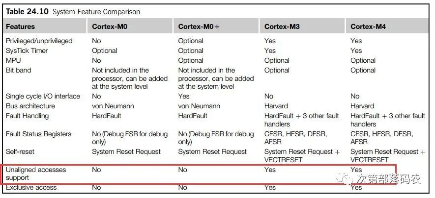
Kernel M7 also supports non-aligned access, as described in the M7 TRM: 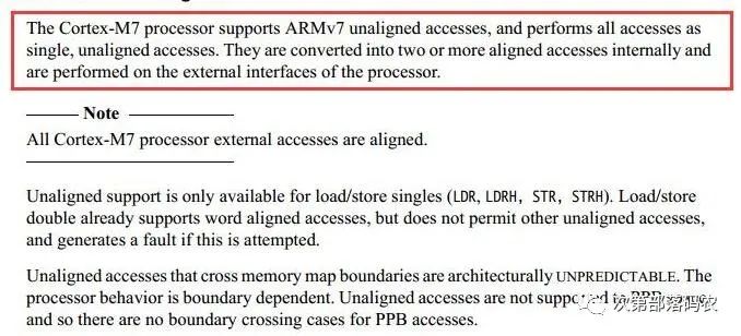
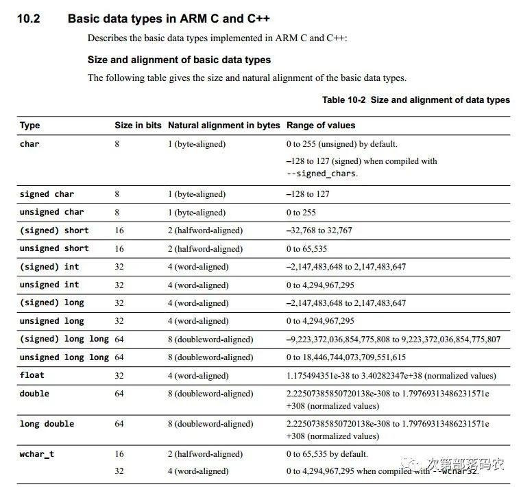
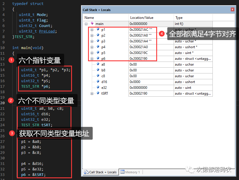
3. Global Variable Alignment Issues: Generally, user-defined variables are aligned according to their byte size, which is easy to understand. uint8_t requires 1-byte alignment. uint16_t requires 2-byte alignment. uint32_t requires 4-byte alignment. uint64_t requires 8-byte alignment. Pointer variables are aligned to 4 bytes.
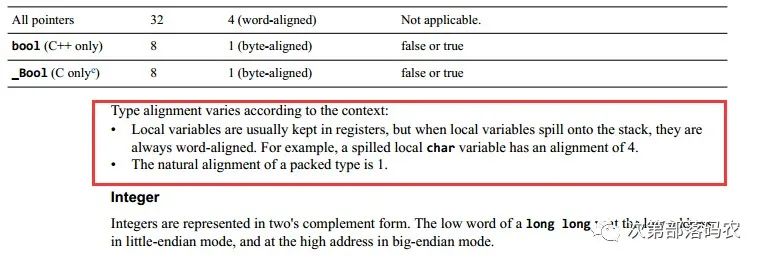 4. Structure Member Alignment Issues: First, understand that the type of variable within a structure dictates the minimum alignment required for that variable, hence the actual size of the structure may not equal the sum of its variables. typedef struct{ uint8_t a; uint16_t b; uint32_t c; uint64_t d; }info; this definition occupies 16 bytes, where a is aligned to 1 byte, b to 2 bytes, and c to 4 bytes, leaving 1 byte unused after b. d requires 8-byte alignment, resulting in a total of 16 bytes. If we change the order of variable definitions: typedef struct{ uint16_t b; uint32_t c; uint64_t d; uint8_t a;}info; this definition occupies 24 bytes, where b occupies 2 bytes, c requires 4 bytes, leaving 2 bytes unused, while d occupies 8 bytes, and the last a occupies 8 bytes. If we want to define a few variables to occupy exactly their byte size, we can add the prefix __packed. Regardless of the above definition methods, it will occupy 15 bytes. __packed typedef struct{ uint8_t a; 1 byte uint16_t b; 2 bytes uint32_t c; 4 bytes uint64_t d; 8 bytes }info;5. Local Variable Alignment Issues: Local variables use stack space (except for static local variables and compiler optimizations that do not use the stack but directly use registers for variable space), which is the stack space allocated in the xxxx.S startup file. In M cores, the alignment issue of local variables can be the most challenging, involving the AAPCS (Procedure Call Standard for the Arm Architecture).
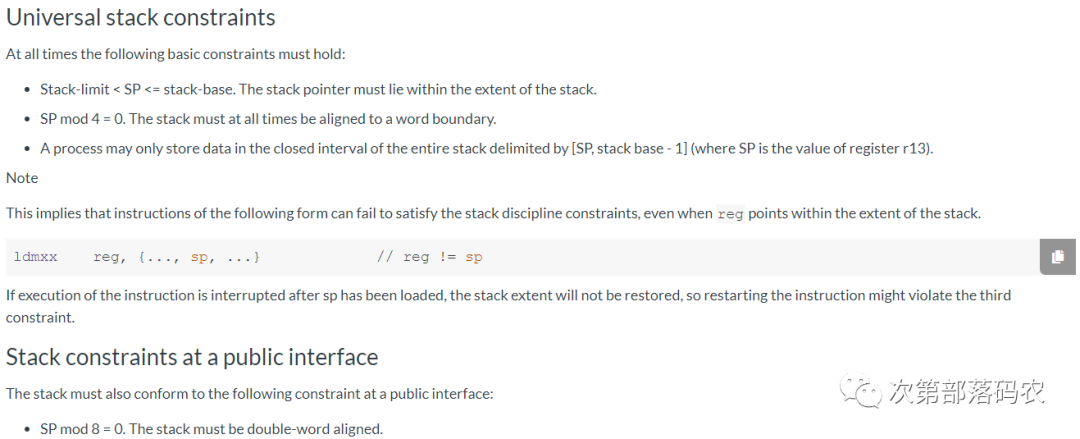
The most important thing in the above image is to understand the following two points: stack addresses must maintain at least 4-byte alignment throughout, as the hardware of the M core has processed this, fixing the lowest two bits of SP to 0. However, at the program entry point, 8-byte alignment must be satisfied. For C language, users do not need to worry; the compiler handles it for us. Here’s a simple example to illustrate:
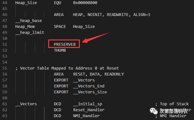
Assembly files require users to handle this. For example, in the xxx.S startup file, use the pseudo-instruction PRESERVE8 to ensure
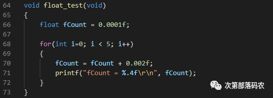
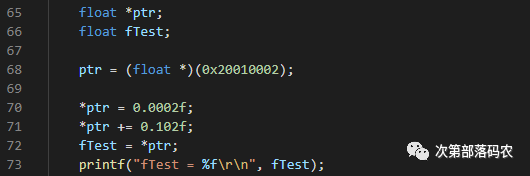
Now the question arises, is there a problem with 4-byte alignment? Generally, there is no issue, but in special cases, it can be problematic, especially when calling C library functions like sprintf and printf, which may yield unexpected results. For example, I conducted the following test on H7:
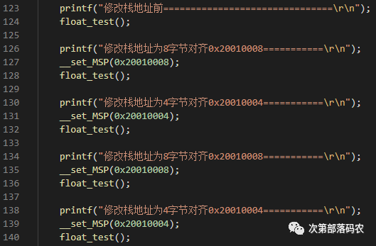
Output results:

6. Stack Alignment Issues in Interrupt Service Routines: Let’s look at two images:
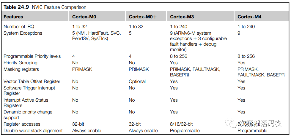
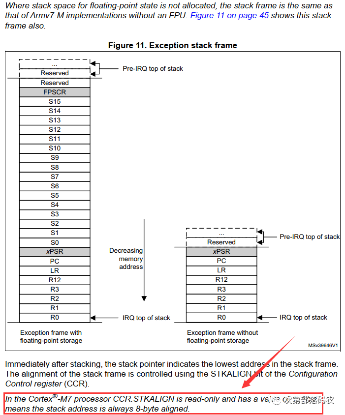
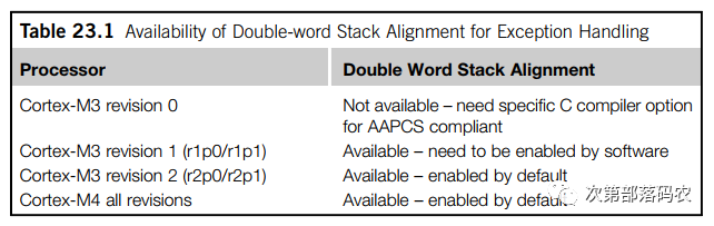
From these two images, we learn that the stack addresses of M0/M0+/M7 are fixed to 8-byte alignment, while M3/M4 can program the SCB->CCR register for 4-byte or 8-byte alignment. For instance, if we set it to 8-byte alignment, when an interrupt occurs and the SP pointer is at a 4-byte alignment, the hardware automatically inserts 4 bytes to ensure 8-byte alignment, followed by the hardware automatically pushing the registers onto the stack.
Additionally, different hardware versions of the M core may vary slightly in this regard, but this is just for reference; early hardware versions of the core are likely no longer in use.
7. Hardware Floating Point Alignment Issues: If using an M core chip with an FPU hardware floating-point unit, note that access to single-precision floating-point numbers must be 4-byte aligned, while double-precision must be 8-byte aligned. For instance, using an M4 core chip that supports single-precision floating-point, the test code is as follows:
The MDK directly triggers an unaligned hardware exception:
 8. RTOS Task Stack: The RTOS task stack involves the dual stack pointer problem, SP (R13 register) has two stack pointers, the MSP main stack pointer and the PSP process stack pointer. In simple terms, we use MSP in interrupt service routines, while PSP is used in tasks. The advantage is that it facilitates separate management of task and interrupt stack spaces; understanding this knowledge is sufficient. The key issue with the RTOS task stack is still the 8-byte alignment problem. If only 4-byte alignment is satisfied, we will encounter the earlier mentioned printf and sprintf floating-point or 64-bit data error issues. In the earlier days when various RTOS porting cases were not so developed (and the problem still persists today), many pitfalls arose in this area, and with the hardware floating-point registers pushed onto and popped off the stack, it becomes even more challenging. For example, if you search keywords like uCOS printf or uCOS floating-point, you’ll find a plethora of issues. If you don’t use floating-point operations, you might not notice, but once you do, various problems arise, especially when multiple tasks use floating-point calculations, it can be quite bewildering. The root cause is the stack alignment issue in the underlying port file; many people use the instruction __align(8) to set the stack alignment, but modifying the underlying port file is the fundamental solution. Why does this problem occur? The root cause still lies in the requirements of the AAPCS regulations; RTOS porting includes an assembly port file, and the key to task switching is ensuring that the PSP is 8-byte aligned before entering the task.
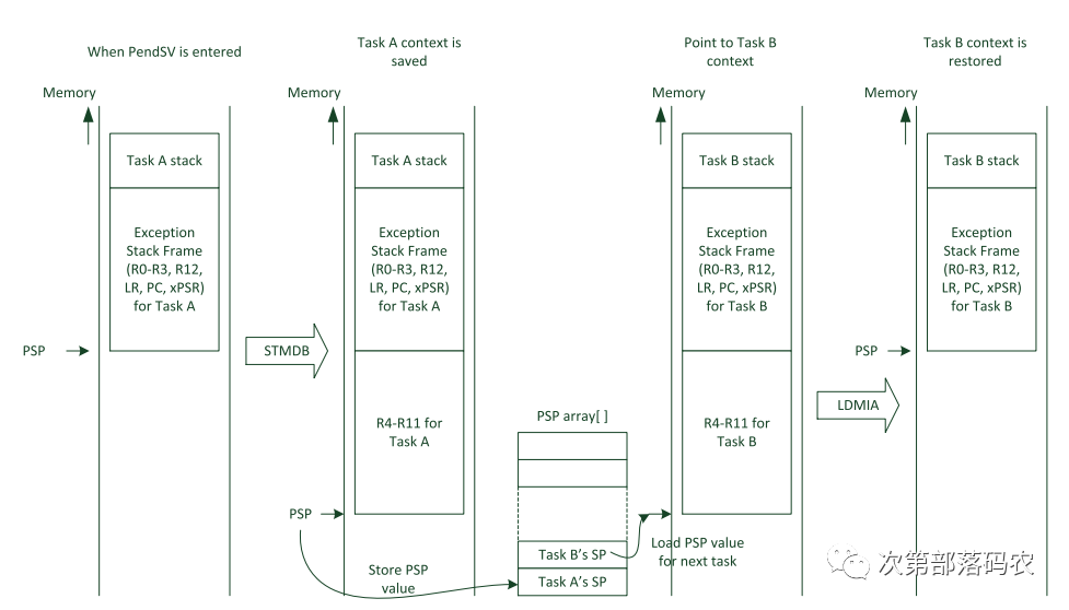
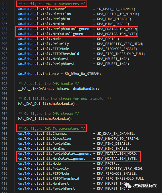
9. DMA Alignment Issues: DMA alignment refers to the issue of source data address and destination data alignment. The most common place for errors is when transferring SD card data using FatFS in SDIO DMA mode. Searching keywords like FatFS SDIO DMA online reveals a plethora of issues, especially when displaying images in formats like BMP, as it is difficult to ensure that each read is 4-byte aligned. Taking the STM32F4’s DMA as an example, our lower-level porting does not require a separate buffer for 4-byte alignment; essentially, the F4 DMA supports different data widths for source and destination addresses, but the data addresses must be aligned to their data types. For example, when using SDIO DMA to read data from the SD card, we can set the source address to remain 4-byte aligned (peripheral access must be 4-byte aligned), while the destination address can be set to byte-aligned, conveniently resolving the 4-byte alignment issue.
In fact, not just general DMA, but also graphic acceleration DMA2D, and IDMA that comes with SDMMC have similar issues.
Using DMA to transfer ADC data has always been done using the rule injection method, but after configuring a new project a few days ago, I found that the data was half of what it used to be. After checking for four hours, I finally discovered the problem, and I’m sharing this record.
Therefore, in cubemx, the corresponding DMA transmission data width should also be selected as ‘word’ corresponding to it.
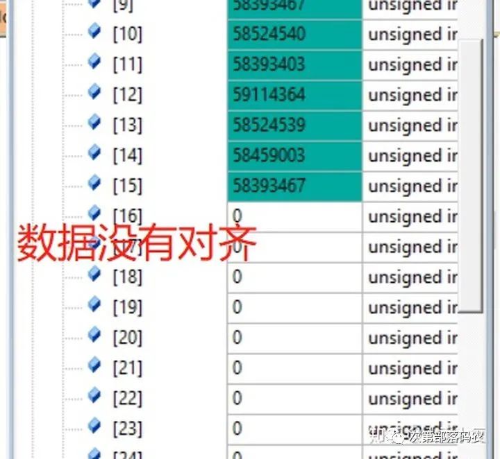
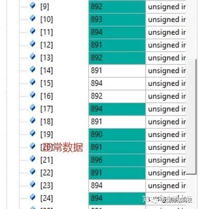
Using the above anomalous data, the calculated result is obviously half of the normal data. To avoid such issues, if there aren’t as many channel data, you can use the triggered injection method for collection; this is simpler and more convenient, but it requires setting a trigger signal.
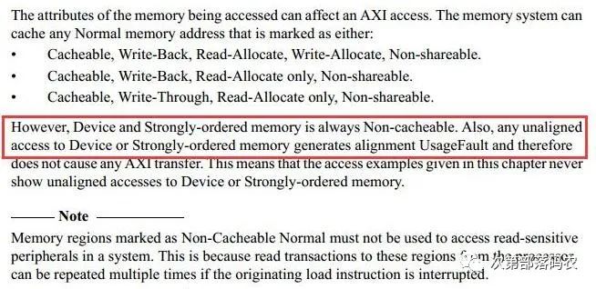
10. Alignment Issues Caused by MPU Configuration: This issue mainly concerns M7 core chips, taking STM32H7 TCM external space as an example: AXI RAM (0x2400 0000), SRAM1 (0x3000 0000), SRAM2 (0x3002 0000), SRAM3 (0x3004 0000), SRAM4 (0x3800 0000), SDRAM, etc., will trigger hardware exceptions for non-aligned accesses, while enabling Cache will not have issues. The key to this problem lies in this statement from the M7’s TRM: meaning that if a user configures the memory space under the H7’s AXI bus as Device or Strongly-ordered mode, non-aligned access will trigger UsageFault.
In actual sequencing, this exception is indeed triggered.
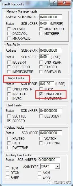
Configuring the MPU attributes of the memory space as anything other than Device and Strongly-ordered can solve this issue.