0. Introduction
0. Introduction
Bluetooth, as a widely used communication protocol, has seen rapid growth in numbers in recent years. According to market research, in 2021, the shipment of Bluetooth devices reached 4.7 billion units and is expected to exceed 7 billion units by 2026. Bluetooth devices are typically deployed in physical hardware, so if there are vulnerabilities, it may lead to information leakage, economic losses, and even threats to personal safety. Like other firmware devices, the firmware updates for Bluetooth devices are often delayed, and some Bluetooth devices cannot perform hot updates. Therefore, it is necessary to conduct software testing on the firmware of Bluetooth devices.
Fuzz testing technology is a software testing method that is faster and less resource-intensive compared to symbolic execution technology, and it has become a popular and effective vulnerability mining method in recent years. Fuzz testing involves inputting randomly generated test cases into a program and monitoring the program’s runtime status and exceptions to detect potential program vulnerabilities. Research has shown that fuzz testing technology is an effective method and has successfully mined a large number of software vulnerabilities. With ongoing research, researchers have applied fuzz testing technology to various protocols and firmware software testing. By studying vulnerability mining methods for firmware Bluetooth protocol stacks, we can better perform software testing on firmware Bluetooth protocol stacks, thus protecting the information security and even personal safety of Bluetooth device users, reducing economic losses caused by vulnerabilities, and maintaining the security and stability of cyberspace.
1. Related Technology Introduction
1. Related Technology Introduction
1.1 Protocol Fuzz Testing
Currently, many gray-box fuzz testing tools have been widely recognized in both industry and academia. However, these research efforts are not suitable for protocol testing. On one hand, the server usually has a state machine model, and the client needs to send requests to the server to advance the server’s current state; otherwise, inputs will be discarded by the server at an early stage, making it impossible to detect deeper paths. On the other hand, protocols often have certain syntax and semantic rules, and merely using byte-level mutation algorithms will generate a large number of invalid inputs.
In recent years, tools for protocol fuzz testing have emerged, such as AFLNET and StateAFL. Additionally, there are tools developed for specific protocols, such as ICS3Fuzzer and TCP-Fuzz. Among these solutions, AFLNET is a more representative tool. AFLNET uses message sequences as seed files, extracting rough server state changes by parsing the server’s response packets and recording the state changes caused by each packet in the seed file. Through this method, a state machine change model for the server is constructed on the client side, while splitting the seed file into M1, M2, M3, etc. During the fuzz testing process, AFLNET tests only one server’s current state at a time, a method that has proven to be very effective.
1.2 Firmware Fuzz Testing
The primary task when fuzz testing firmware programs is to build a simulation environment. This is because firmware devices have limited hardware resources, and relying solely on firmware devices for fuzz testing is inefficient and cannot be scaled. To establish a simulation environment for firmware programs, the interaction between the firmware program and peripheral devices must be considered, primarily including interrupts, Direct Memory Access (DMA), and Memory-mapped I/O (MMIO). Among these interactions, MMIO is commonly present, so implementing the interaction between firmware programs and MMIO is a key factor to consider when building firmware simulation environments. The fuzz testing solutions for firmware mainly include the following:
(1) Hardware-participated solutions. Representative works of this approach include Avatar2 and Inception. Although this method has certain effects, it has some issues. First, it lacks universality and cannot be applied to all firmware devices. Second, the operation is very slow when forwarding or resetting the firmware device’s state in the next fuzz testing cycle, which becomes a performance bottleneck for fuzz testing.
(2) Abstract replacement solutions. Representative works of this approach include HALucinator and Firmadyne. The core idea of this method is to avoid MMIO access by the firmware program, achieving this by bypassing the interaction between the firmware program and peripheral devices. However, this requires a lot of manual work to bypass MMIO access by the firmware program, leading to poor adaptability.
(3) Full simulation solutions. This approach resolves the interaction issues of firmware programs and peripheral devices by re-implementing hardware devices in the simulator. Representative work includes Quick EMUlator (QEMU). Although this solution can accurately simulate MMIO, it requires a deep understanding of hardware documentation and manual coding to re-implement hardware device code, thus having a high degree of engineering and relatively few related research works.
1.3 Bluetooth Fuzz Testing
Currently, there is still relatively little research on Bluetooth fuzz testing both domestically and internationally, with representative solutions including Frankenstein and Sweyntooth.
Frankenstein testing targets mobile phone Bluetooth modules and is implemented based on a QEMU virtualization solution. This solution collects runtime information from the simulated CPU to obtain program coverage. In mobile Bluetooth, the host is located on the Application Processor (AP) chip, while the Bluetooth controller is located on the Bluetooth chip. Frankenstein supports fuzz testing of the controller by attaching the host to the Linux BlueZ Bluetooth protocol stack.
The Sweyntooth solution considers the issue that general fuzz testing tools cannot effectively fuzz test Bluetooth protocols, adding a protocol state machine to its fuzz testing framework to avoid generating a large number of invalid test cases. Additionally, this solution has incorporated more effective mutation algorithms for fuzz testing Bluetooth data packets. These algorithms include mutating specific Bluetooth fields through heuristic algorithms and repeatedly testing Bluetooth data packets in incorrect states. These improvements enable the Sweyntooth solution to fuzz test Bluetooth protocols more accurately and efficiently.
2. Overall Process and Core Module Design
2. Overall Process and Core Module Design
This paper studies, designs, and implements a fuzz testing solution for firmware Bluetooth protocol stacks based on virtualization, called BBFirmBTFuzz. Firmware Bluetooth protocol stacks are typically used in smart home devices, primarily targeting microcontroller (MCU) firmware devices. Therefore, the simulation environment must be suitable for MCU devices, while existing Linux-based research solutions cannot achieve this. This paper provides a running environment for MCU firmware programs using the full simulation environment QEMU.
Compared to desktop operating systems, the hardware environment resources for firmware are limited. For example, the expat firmware compiled in bare-metal mode is about 100 KiB, suitable for development boards like STM32XXXXXB (128KB Flash); while the GATT Server (Generic Attribute Profile) firmware compiled in real-time operating system (RTOS) mode is about 230 KB, only suitable for development boards with STM32XXXXXC (256KB Flash) and above. This paper simulates multiple devices to support both RTOS firmware programs and bare-metal firmware programs, as well as simulating the Bluetooth controller to facilitate fuzz testing of firmware Bluetooth protocol stacks.
The overall process of the framework is shown in Figure 1.
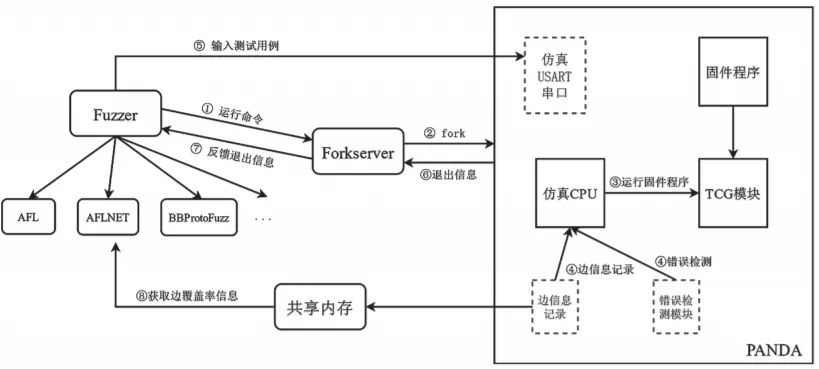
Figure 1: Architecture of the Fuzz Testing Solution for Firmware Bluetooth Protocol Stacks Based on Virtualization
The macro structure of this solution is consistent with AFL, divided into three parts: Fuzzer, Forkserver, and Target.
(1) Fuzzer: Responsible for the logical control of fuzz testing and the mutation of test cases. Any fuzz testing engine designed using the AFL architecture can serve as the Fuzzer for this framework.
(2) Forkserver: Responsible for starting the Target and collecting the exit reasons of the Target.
(3) Target: PANDA is the actual Target running the firmware program. It is responsible for collecting edge coverage information of the firmware program during its execution, detecting errors while the firmware program runs, and receiving test case inputs through the emulation of a Universal Synchronous Asynchronous Receiver Transmitter (USART) serial port. To fuzz test the firmware Bluetooth protocol stack, both RTOS firmware programs and bare-metal firmware programs are supported, and the architecture of the firmware Bluetooth protocol stack virtualization solution is shown in Figure 2.
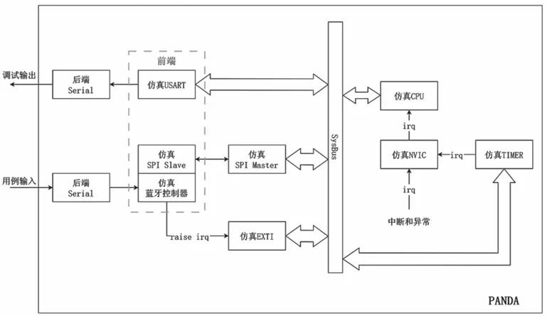
Figure 2: Architecture of the Firmware Bluetooth Protocol Stack Virtualization Solution
All simulated devices can pass the Nested Vectored Interrupt Controller (NVIC) to deliver interrupts and exceptions to the simulated CPU at any time. When the simulated CPU finishes translating the current basic block, it will handle the generated interrupts and exceptions. This process typically involves stack operations, executing Interrupt Service Routines (ISRs), and popping the stack. Each value of an IRQ (interrupt request) corresponds to an ISR entry in the interrupt vector table. In ARMv7-M chips, QEMU only enables the first 16 entries (excluding reserved parts), which are common in ARMv7-M chips. Subsequent ISR entries will vary in different hardware environments. Therefore, when implementing the simulation environment, it is necessary to manually enable the required ISR entries, such as enabling the EXTI0 interrupt entry in BBFirmBTFuzz.
The function of the simulated NVIC is to notify the simulated CPU that an interrupt with vector number X has occurred. When the simulated CPU processes this interrupt, it will retrieve the address of the ISR from the interrupt vector table stored in SRAM based on the interrupt vector number and assign it to the Program Counter (PC) register, thus completing the interrupt operation. The interrupt vector table is first stored at the starting address of Flash memory, which is by default 0x08000000 in STM32L152RE. During the initialization phase, the interrupt vector table is copied to the starting address of SRAM, which is by default 0x20000000 in STM32L152RE. Subsequently, during the initialization phase, the required ISRs will be registered in the interrupt vector table. Ultimately, the complete interrupt vector table is stored at the starting address of SRAM.
Since fuzz testing uses snapshots at the main function of the application, it eliminates the lengthy initialization process of the firmware program, so for the target, the complete interrupt vector table is stored at the starting address of SRAM.
Timers are widely used in various operating systems, for example, when executing wait seconds (wait_s), milliseconds (wait_ms), microseconds (wait_us), etc. Even in bare-metal mode, timers can be implemented through loop interrupts. In the STM32 hardware environment, when the simulated CPU needs to execute a timed task, it modifies the timer’s preload register to set a timed task. When the waiting time is reached, the timer will generate an interrupt to notify the simulated CPU.
2.1 Building Minimal Simulation Devices
This section will introduce how to build the simplest onboard simulation device. In fact, building a simulation device is an engineering task, and each simulation device is associated with a specific hardware environment. To realize a simulation device, it is usually necessary to refer to the user manual and data sheet of the hardware environment. Although building basic simulation devices requires some manual involvement, it does not actually take much time. Subsequently, the simulation devices can be expanded according to needs. However, developing a mature firmware fuzz testing engineering product requires adapting to different peripheral devices and hardware environments, similar to what QEMU does. This can be a significant workload for individuals.
The onboard peripheral devices are mounted on the system bus, and external peripheral devices connect to the development board via serial ports, such as USART and Serial Peripheral Interface (SPI). For example, the system architecture of development boards like STM32L15XXB and below flash capacity is shown in Figure 3. Therefore, when building simulation devices, it is also necessary to mount them on QEMU’s system bus, which is completed after creating the simulation device object. Setting the attributes for the simulation device object should also be done before realizing (Realized) the simulation device object, such as setting the clock frequency for the timer object.
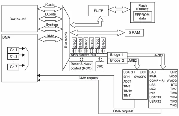
Figure 3: System Architecture of STM32L15XXB
Data is exchanged between peripheral device registers and the CPU through MMIO, and implementing MMIO functionality is the foundation for building simulation devices. For simulation devices, they need to respond to the simulated CPU’s access instructions to the corresponding MMIO areas, including read and write operations. In QEMU, a memory area is used to simulate the various registers of the simulation device. Thus, when the simulated CPU accesses the corresponding MMIO area, the simulation device achieves the effect of simulating a real device by operating on various simulated registers. For the simplest onboard simulation device, when the CPU performs a write operation to the corresponding MMIO, it only needs to assign the value of the source operand to the simulated register. When the CPU performs a read operation to the corresponding MMIO, it only needs to assign the value of the simulated register to the destination operand.
2.2 Simulating SPI Devices and Bluetooth Controllers
In addition to onboard peripheral devices, peripheral devices can also connect to the development board via serial ports like USART and SPI to extend the board’s functionality. In the STM32L152RE hardware environment, although there is no onboard Bluetooth chip, Bluetooth functionality can be achieved by connecting to a Bluetooth expansion board via SPI. Therefore, this section will introduce how to implement Bluetooth functionality in the simulation environment through simulating SPI and simulating Bluetooth controllers.
In the simulation environment, SPI only needs to focus on the parts connected to the bus. In the STM32L152RE hardware environment, SPI is configured by default to operate in full-duplex mode, which is also the usual operating mode for SPI. Therefore, the simulated SPI also needs to operate in full-duplex mode. In full-duplex mode, the SPI Master actively triggers the Master Out Slave In (MOSI) interface, and then the SPI Slave triggers the MISO interface. The MISO interface cannot be actively triggered by the SPI Slave. Therefore, read and write operations are completed synchronously. Specifically, when the program only performs a write operation, the received byte can be ignored; when the program only performs a read operation, an empty byte can be written into the corresponding MMIO to trigger the SPI Slave’s MISO transfer.
The peripheral device registers are represented in QEMU as a block of memory space, with each register corresponding to an access to a specific MMIO area. The CPU exchanges data with the SPI Slave through the SPI_DR register, while the SPI_SR register changes simultaneously. For the simulated SPI Master, the Tx buffer, Shift register, and Rx buffer only exist logically.
The workflow of the simulated SPI Master executing a round of MOSI and MISO operations is as follows:
(1) The simulated CPU performs an MMIO write to the SPI_DR register, which triggers the processing of the simulated SPI Master.
(2) The simulated SPI Master modifies the value of the simulated spi_dr register, sends the data to the SPI Slave for processing, and then saves the data from the MISO back to the simulated spi_dr register while simultaneously changing the simulated spi_sr register.
(3) Since it is in full-duplex mode, the simulated CPU will then perform an MMIO read to the SPI_DR register, causing the simulated SPI Master to return the value from the simulated spi_dr register to the simulated CPU while also changing the simulated spi_sr register.
More detailed workflows, such as changes in the status register (SPI_SR), the role of the shift register, and the MMIO mapping relationships of device registers, can be found in the user manual and data set.
3. Experimental Results Analysis
3. Experimental Results Analysis
This section evaluates the effectiveness of BBFirmBTFuzz by fuzz testing the GATT server compiled in RTOS mode, based on three metrics: performance, path coverage, and the number of new seed files. The target for testing is the Cordio Bluetooth protocol stack, which is a protocol stack developed by ARM specifically designed for low-power, single-mode Bluetooth devices. The Cordio Bluetooth protocol stack is favored for its small code size, user-friendly API interface, and portable architecture, making it an excellent solution for developing low-power Bluetooth products.
Fuzz testing typically uses modules as the testing unit. For modules that do not directly obtain input from stdin/file, a harness needs to be written for testing. This section targets the GATT layer in the Bluetooth protocol stack, using the GATT server of the Cordio Bluetooth protocol stack as a harness for testing.
Figures 4 and 5 respectively show the path coverage and the number of new seeds during the fuzz testing process of the firmware Bluetooth server. Since the experiment uses a snapshot after the firmware program initialization as the target to avoid the lengthy initialization process and improve fuzz testing performance, otherwise, all paths of the real-time operating system startup and initialization would be included. Therefore, the number of paths detected at hour 0 is not many, which is normal, as for the GATT service, most test cases are discarded early in the processing. From Figures 4 and 5, it can be seen that the growth rate of seed files does not match the growth rate of detected paths, which is because, in the early stages of fuzz testing, new seed files have a higher probability of being added to the queue due to triggering new execution logic, while in the later stages of fuzz testing, the number of new seed files is more likely to be added to the queue for other reasons, such as the increase in edge execution counts and the decline in stability (due to the RTOS being a multi-threaded architecture).
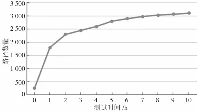
Figure 4: Path Coverage of Fuzz Testing GATT Server

Figure 5: Number of New Seed Files for Fuzz Testing GATT Server
Since this experiment requires supporting the operation of RTOS and Bluetooth modules, more simulated devices have been added, which will further incur performance loss; however, this overhead is acceptable. In this experiment, the execution speed of fuzz testing is about 40 times per second.
The experimental results indicate that BBFirmBTFuzz can correctly fuzz test the Cordio Bluetooth protocol stack, with its execution speed, number of detected paths, seed queue length, and other indicators all within normal ranges.
4. Conclusion
4. Conclusion
This paper designs and implements a fuzz testing method for firmware Bluetooth protocol stacks based on virtualization, called BBFirmBTFuzz. This method supports fuzz testing of RTOS mode compiled firmware programs and firmware Bluetooth protocol stacks through the simulation of various hardware devices. Finally, the effectiveness of the proposed solution is validated through fuzz testing of the Cordio protocol stack.
Original source: Journal of Information Security and Communication Confidentiality: Submission contact: 010-82992251 [email protected]