Effect Demonstration
Persistence of Vision and Flicker Perception: Why Delay Matters? 🤔
In our daily lives, we are often captivated by some magical visual phenomena👀: waving glow sticks at night can create continuous light trails in the air✨; old televisions display frames one by one, yet we perceive them as smooth animations🎞️. Behind these fascinating phenomena lies a key physiological mechanism—persistence of vision! When we control an LED with the ESP32 development board to create a flickering effect, this seemingly unrelated “human eye characteristic” subtly influences the final presentation effect🤯. The sleep() delay setting in the code becomes a crucial link between hardware and visual perception🔗. Now, let’s uncover the mysterious connection between them!
Persistence of Vision: The Eye’s “Time Filter” ⏳
When light enters the eye and projects onto the retina, the neural signals do not disappear immediately with the light source. Instead, they linger in the brain for a short period of 0.05 – 0.1 seconds, as if adding a layer of “time filter”🕶️ to the real world, making the images appear continuous. Just like film frames played at 24 frames per second (each frame about 0.04 seconds), our eyes automatically “stitch” the previous and next images together to see coherent dynamic images🎬. However, if the frame rate is too low (each frame exceeds 0.1 seconds), the images will flicker wildly, causing eye strain😵.
Illustration of the Persistence of Vision PrincipleBold Style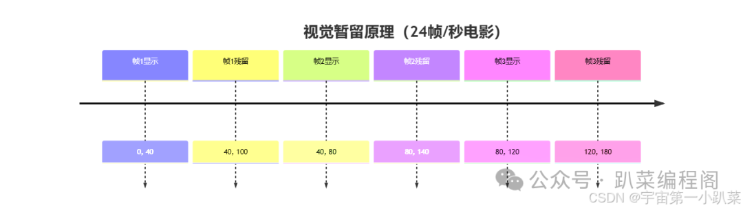
The Impact of Persistence of Vision on LED Flickering 💡
For LED flickering, persistence of vision sets an “invisible threshold”🚪: only when the LED is on and off for more than 0.1 seconds can we clearly distinguish the change. If the off time is too short (for example, 0.01 seconds), the eyes will package it with the previous on state, mistakenly thinking the LED is always on💡.
Visual Effect Comparison of Different Delay Settings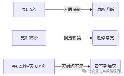
Delay Settings in Code: How to Adapt to Human Eye Characteristics 💻
In the ESP32 code controlling the LED, the parameter of the sleep() function is the “behind-the-scenes operator”🎭 that regulates the on and off times. To make the flickering visible to the naked eye, remember these two tips:
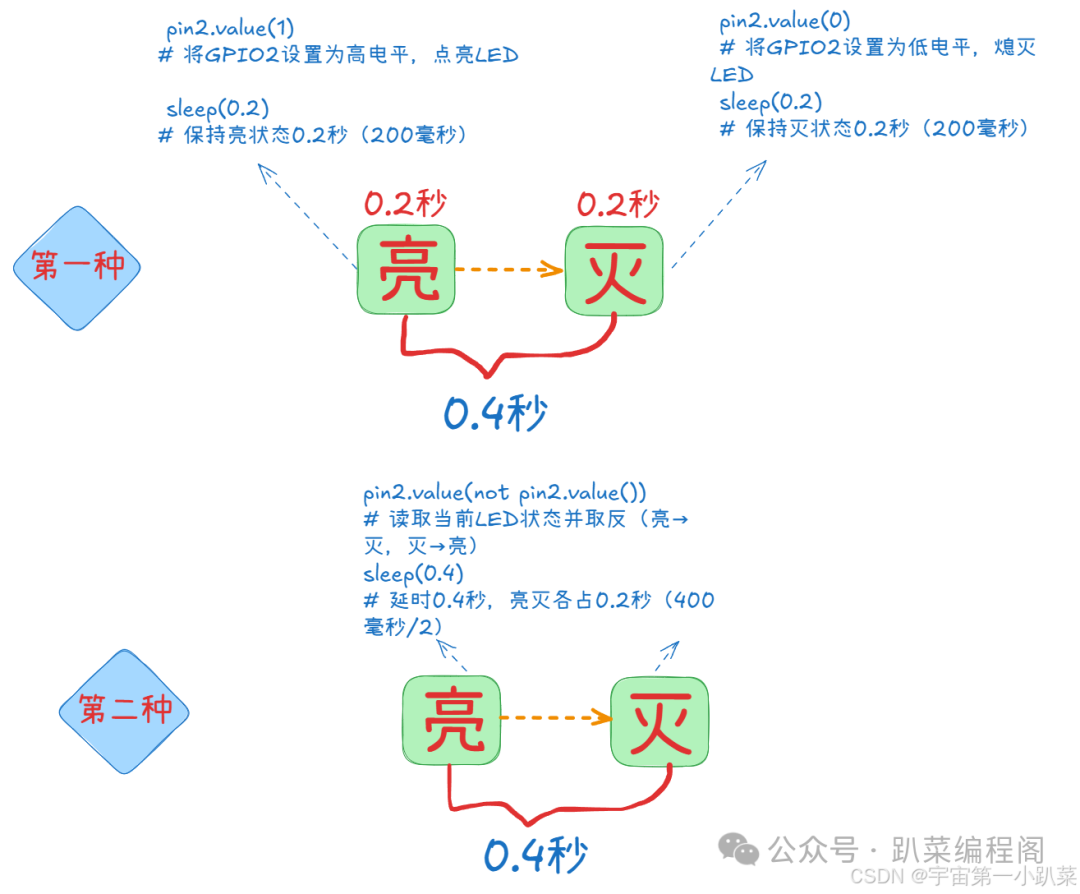
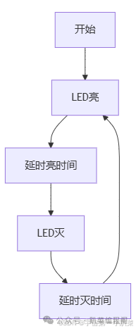
Dual Delay Scheme Execution Flow
from machine import Pin # Import Pin class to control ESP32 GPIO pins
from time import sleep # Import sleep function to control delay
pin2 = Pin(2, mode=Pin.OUT) # Configure GPIO2 as output mode, connect to LED
# Dual delay scheme: control on and off times with two independent delays
while True: # Infinite loop to keep LED flashing
pin2.value(1) # Set GPIO2 to high, turn on LED
sleep(0.2) # Keep on state for 0.2 seconds (200 milliseconds)
pin2.value(0) # Set GPIO2 to low, turn off LED
sleep(0.2) # Keep off state for 0.2 seconds (200 milliseconds)
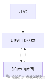
# On and off times are both ≥0.1 seconds, visible flicker to the human eye✨Single Delay Scheme Execution Flow
from machine import Pin       # Import Pin class to control ESP32 GPIO pins
from time import sleep        # Import sleep function to control delay

pin2 = Pin(2, mode=Pin.OUT)   # Configure GPIO2 as output mode, connect to LED

# Single delay scheme: automatically allocate on and off times through total delay (each takes half)
while True:                   # Infinite loop to keep LED flashing
    pin2.value(not pin2.value())  # Read current LED state and invert (on→off, off→on)
    sleep(0.4)                # Delay for 0.4 seconds, on and off each take 0.2 seconds (400 milliseconds/2)
    # Total cycle ≥0.2 seconds, on and off times are both ≥0.1 seconds, visible flicker to the human eye✨
Essential Analysis: On → Off Cycle is 0.4 Seconds 🔄
First Scheme
from machine import Pin       # Import Pin class to control ESP32 GPIO pins
from time import sleep        # Import sleep function to control delay

pin2 = Pin(2, mode=Pin.OUT)   # Configure GPIO2 as output mode, connect to LED

# Dual delay scheme: control on and off times with two independent delays
while True:                   # Infinite loop to keep LED flashing
    pin2.value(1)             # Set GPIO2 to high, turn on LED
    sleep(0.2)                # Keep on state for 0.2 seconds (200 milliseconds)
    pin2.value(0)             # Set GPIO2 to low, turn off LED
    sleep(0.2)                # Keep off state for 0.2 seconds (200 milliseconds)
    # On and off times are both ≥0.1 seconds, visible flicker to the human eye✨
Second Scheme
from machine import Pin       # Import Pin class to control ESP32 GPIO pins
from time import sleep        # Import sleep function to control delay

pin2 = Pin(2, mode=Pin.OUT)   # Configure GPIO2 as output mode, connect to LED

# Single delay scheme: automatically allocate on and off times through total delay (each takes half)
while True:                   # Infinite loop to keep LED flashing
    pin2.value(not pin2.value())  # Read current LED state and invert (on→off, off→on)
    sleep(0.4)                # Delay for 0.4 seconds, on and off each take 0.2 seconds (400 milliseconds/2)
    # Total cycle ≥0.2 seconds, on and off times are both ≥0.1 seconds, visible flicker to the human eye✨
Core Logic Comparison
| Scheme Type | On Operation Logic | Off Operation Logic | Total Cycle | Code Characteristics |
|---|---|---|---|---|
| First Scheme | Explicitly set high (<span>value(1)</span>) |
Explicitly set low (<span>value(0)</span>) |
0.4 seconds | Step-by-step control, intuitive logic |
| Second Scheme | Invert state (<span>not value()</span>) |
Maintain off state through delay “automatically” | 0.4 seconds | Simpler code, relies on state inversion |
-
First Scheme (Dual Delay: Explicit Control of On and Off)
- Steps: Turn on LED → Delay 0.2 seconds (keep on) → Turn off LED → Delay 0.2 seconds (keep off).
- Cycle: On 0.2 seconds + Off 0.2 seconds = 0.4 seconds, completing one “On→Off” cycle.
-
Characteristics: Intuitive logic, controls on and off durations through two explicit delays, suitable for beginners to understand the “separation of on and off” logic.
-
Second Scheme (Single Delay: State Inversion)
- Steps: Switch LED state (On ↔ Off) → Delay 0.4 seconds (maintain current state).
- Cycle: Since the state will invert, the delay of 0.4 seconds will be split into “On 0.2 seconds + Off 0.2 seconds” (essentially consistent with the first scheme’s cycle).
-
Characteristics: Code is simpler, automatically inverts state through not pin2.value(), but requires understanding the implicit logic of “total delay = on and off cycle”.
- Essential Connection
- Both schemes have an “On→Off total cycle of 0.4 seconds”, differing only in implementation:
- First: Split on and off steps, controlling with two delays.
- Second: Merge state inversion, covering the complete cycle with one delay.
Chart Display