Follow+Star Public Account Number, don’t miss out on exciting content

Author | strongerHuang
WeChat Public Account | strongerHuang
When we learn about microcontrollers, the first thing we might encounter is lighting up (GPIO), and then it’s serial communication (UART).
Serial communication is a commonly used communication interface and is essential knowledge for learning embedded systems. However, I have found that many friends only know how to use the serial port to output or print some data, but do not know how to use the serial port for data transmission and communication.
Here, I will share with you the serial communication protocol, custom communication protocols, and the principles of implementation.
What is a communication protocol?
A communication protocol is not difficult to understand; it is a set of rules that must be followed for communication between two (or more) devices.
The Baidu Encyclopedia explains:
A communication protocol refers to the rules and agreements that both parties must follow to complete communication or services. For multiple data communication systems connected through communication channels and devices at different geographical locations to work together to achieve information exchange and resource sharing, they must have a common language. What to communicate, how to communicate, and when to communicate must follow some mutually acceptable rules. This rule is the communication protocol.
Many readers may have purchased some modules based on serial communication. Many of the modules on the market use custom communication protocols, some of which are relatively simple, while others are a bit more complex.
For example, a very simple serial communication protocol: for instance, transmitting only a temperature value, which consists of only three bytes:
Frame Header
Temperature Value
Frame Tail
|
5A |
One-byte value |
3B |
Doesn’t this seem very simple? It is also a type of communication protocol.
It is just that this communication protocol is relatively simple in application (between two devices one-to-one), and it has many drawbacks.
Problems with simple communication protocols
The above three-byte communication protocol is something everyone can understand. Although it can communicate and transmit data, it has a series of problems.
For example: how to determine who to transmit to when multiple devices are connected on a single bus (like RS-485)? (No device information)
Also: in an interference environment, can you ensure the data transmission is correct? (No checksum information)
Furthermore: if I want to transmit multiple data of uncertain length, what should I do? (No length information).
Friends who have done custom communication will understand this series of problems.
Therefore, more “protocol information” must be agreed upon in the communication protocol to ensure the integrity of communication.
Common contents of communication protocols
Serial-based communication protocols usually cannot be too complex due to the serial communication rate, anti-interference capability, and other factors. Compared to TCP/IP communication protocols, they are a lightweight communication protocol.
Therefore, in serial communication, apart from some common communication protocols (like Modbus, MAVLink), engineers often customize communication protocols based on their project requirements.
Below are some key points about common custom communication protocols.
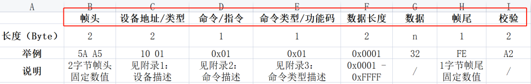
(These are some common protocol contents, which may vary in different situations)
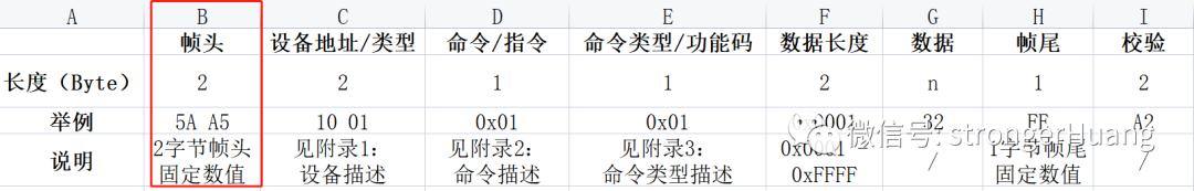
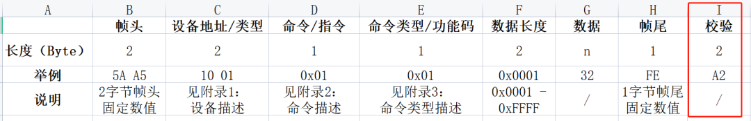
1. Frame Header
The frame header is the beginning of a frame of communication data.
Some communication protocols have only one frame header, while others have two, such as: 5A, A5 as frame headers.
2. Device Address/Type
The device address or device type is usually used between multiple devices to facilitate distinguishing different devices.

In this case, the protocol or appendix must describe various device type information to facilitate developers’ coding and querying.
Of course, for some fixed two-device communication, this option may not be necessary.
3. Command/Instruction
Commands/instructions are quite common, generally distinguishing different operations with different commands.

For example: Temperature: 0x01; Humidity: 0x02;
4. Command Type/Function Code
This option further supplements the command. For example: read, write operations.
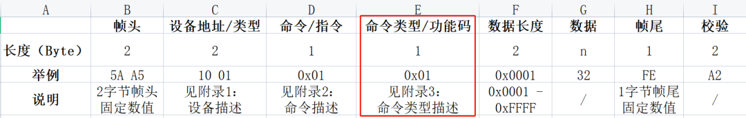
For example: Read Flash: 0x01; Write Flash: 0x02;
5. Data Length
This option for data length may be placed before the device address in some protocols, counting the command and other information as part of the “length”.
This is mainly to facilitate the protocol (receiver) to parse the data length received.
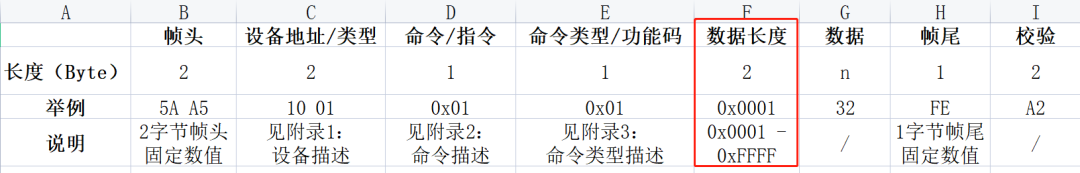
For example: sometimes transmitting valid data, sometimes needing to transmit multiple valid data, or even transmitting an array of data. In this case, the transmitted frame data is variable-length, and it must have【data length】 to constrain it.
Some lengths are one byte, with a range of: 0x01 ~ 0xFF, while others may require more to be transmitted at once, using two bytes to represent a range of 0x0001 ~ 0xFFFFF.
Of course, some communication lengths are fixed (for example, only transmitting temperature and humidity data), and their protocols may not have this option.
6. Data
Data does not need to be described; it is the actual data you are transmitting, such as temperature: 25℃.
7. Frame Tail
Some protocols may not have a frame tail; this should be an optional feature.
8. Checksum
The checksum is a relatively important content; generally, a more formal communication protocol has this option, for a simple reason: communication is easily affected by interference or other reasons, leading to transmission errors.
If there is a checksum, it can effectively avoid data transmission errors.
There are many ways to calculate checksums, with checksums and CRC checks being quite common methods used in custom protocols.
Additionally, some protocols may place the checksum in the second-to-last position, with the frame tail at the end.
Implementation of Communication Protocol Code
There are many ways to implement custom communication protocols in code; how to say it, “All roads lead to Rome”; you just need to write the implementation code according to your protocol.
Of course, while implementing, you need to consider your project’s actual situation, such as if the communication data is relatively large, you need to use a message queue (FIFO), and if the protocol is complex, it is best to encapsulate structures, etc.
Below are some codes I have used before; they may not describe more details, but some ideas can be referenced.
1. Sending Message Data
a. Sending each byte directly through the serial port
This is understandable even for beginners; here is an example from a previous DGUS serial screen:
#define DGUS_FRAME_HEAD1 0xA5 //DGUS screen frame head 1#define DGUS_FRAME_HEAD2 0x5A //DGUS screen frame head 2#define DGUS_CMD_W_REG 0x80 //DGUS write register command#define DGUS_CMD_R_REG 0x81 //DGUS read register command#define DGUS_CMD_W_DATA 0x82 //DGUS write data command#define DGUS_CMD_R_DATA 0x83 //DGUS read data command#define DGUS_CMD_W_CURVE 0x85 //DGUS write curve command/* DGUS register addresses */#define DGUS_REG_VERSION 0x00 //DGUS version#define DGUS_REG_LED_NOW 0x01 //LED backlight brightness#define DGUS_REG_BZ_TIME 0x02 //Buzzer duration#define DGUS_REG_PIC_ID 0x03 //Display page ID#define DGUS_REG_TP_FLAG 0x05 //Touch coordinate update flag#define DGUS_REG_TP_STATUS 0x06 //Coordinate status#define DGUS_REG_TP_POSITION 0x07 //Coordinate position#define DGUS_REG_TPC_ENABLE 0x0B //Touch enable#define DGUS_REG_RTC_NOW 0x20 //Current RTC//Write one byte of data to the specified register of the DGUS screenvoid DGUS_REG_WriteWord(uint8_t RegAddr, uint16_t Data){ DGUS_SendByte(DGUS_FRAME_HEAD1); DGUS_SendByte(DGUS_FRAME_HEAD2); DGUS_SendByte(0x04); DGUS_SendByte(DGUS_CMD_W_REG); //Command DGUS_SendByte(RegAddr); //Address DGUS_SendByte((uint8_t)(Data>>8)); //Data DGUS_SendByte((uint8_t)(Data&0xFF));}//Write one byte of data to the specified address of the DGUS screenvoid DGUS_DATA_WriteWord(uint16_t DataAddr, uint16_t Data){ DGUS_SendByte(DGUS_FRAME_HEAD1); DGUS_SendByte(DGUS_FRAME_HEAD2); DGUS_SendByte(0x05); DGUS_SendByte(DGUS_CMD_W_DATA); //Command DGUS_SendByte((uint8_t)(DataAddr>>8)); //Address DGUS_SendByte((uint8_t)(DataAddr&0xFF)); DGUS_SendByte((uint8_t)(Data>>8)); //Data DGUS_SendByte((uint8_t)(Data&0xFF));}b. Sending through a message queue
Based on the above, use a buffer to hold the message, then “pack” it into the message queue and send it out via the message queue (FIFO).
static uint8_t sDGUS_SendBuf[DGUS_PACKAGE_LEN];//Write one byte of data to the specified register of the DGUS screenvoid DGUS_REG_WriteWord(uint8_t RegAddr, uint16_t Data){ sDGUS_SendBuf[0] = DGUS_FRAME_HEAD1; //Frame head sDGUS_SendBuf[1] = DGUS_FRAME_HEAD2; sDGUS_SendBuf[2] = 0x06; //Length sDGUS_SendBuf[3] = DGUS_CMD_W_CTRL; //Command sDGUS_SendBuf[4] = RegAddr; //Address sDGUS_SendBuf[5] = (uint8_t)(Data>>8); //Data sDGUS_SendBuf[6] = (uint8_t)(Data&0xFF); DGUS_CRC16(&sDGUS_SendBuf[3], sDGUS_SendBuf[2] - 2, &sDGUS_CRC_H, &sDGUS_CRC_L); sDGUS_SendBuf[7] = sDGUS_CRC_H; //Checksum sDGUS_SendBuf[8] = sDGUS_CRC_L; DGUSSend_Packet_ToQueue(sDGUS_SendBuf, sDGUS_SendBuf[2] + 3);}//Write one byte of data to the specified address of the DGUS screenvoid DGUS_DATA_WriteWord(uint16_t DataAddr, uint16_t Data){ sDGUS_SendBuf[0] = DGUS_FRAME_HEAD1; //Frame head sDGUS_SendBuf[1] = DGUS_FRAME_HEAD2; sDGUS_SendBuf[2] = 0x07; //Length sDGUS_SendBuf[3] = DGUS_CMD_W_DATA; //Command sDGUS_SendBuf[4] = (uint8_t)(DataAddr>>8); //Address sDGUS_SendBuf[5] = (uint8_t)(DataAddr&0xFF); sDGUS_SendBuf[6] = (uint8_t)(Data>>8); //Data sDGUS_SendBuf[7] = (uint8_t)(Data&0xFF); DGUS_CRC16(&sDGUS_SendBuf[3], sDGUS_SendBuf[2] - 2, &sDGUS_CRC_H, &sDGUS_CRC_L); sDGUS_SendBuf[8] = sDGUS_CRC_H; //Checksum sDGUS_SendBuf[9] = sDGUS_CRC_L; DGUSSend_Packet_ToQueue(sDGUS_SendBuf, sDGUS_SendBuf[2] + 3);}c. Using a “structure” instead of an array “SendBuf” method
Structures are more convenient for referencing and managing than arrays, so the structure method is more advanced and practical than the array buffer method. (Of course, if there are many members, using temporary variables may also lead to excessive stack usage)
For example:
typedef struct{ uint8_t Head1; //Frame head 1 uint8_t Head2; //Frame head 2 uint8_t Len; //Length uint8_t Cmd; //Command uint8_t Data[DGUS_DATA_LEN]; //Data uint16_t CRC16; //CRC checksum}DGUS_PACKAGE_TypeDef;d. More
There are many ways to send data via serial, such as using DMA instead of the message queue method.
2. Receiving Message Data
Serial message reception is usually done through serial interrupts, although there are rare cases where polling is used to receive data.
a. Conventional Interrupt Reception
Using the DGUS serial screen as an example, here is a simple and common interrupt reception method:
void DGUS_ISRHandler(uint8_t Data){ static uint8_t sDgus_RxNum = 0; //Count static uint8_t sDgus_RxBuf[DGUS_PACKAGE_LEN]; static portBASE_TYPE xHigherPriorityTaskWoken = pdFALSE; sDgus_RxBuf[gDGUS_RxCnt] = Data; gDGUS_RxCnt++; /* Check frame header */ if(sDgus_RxBuf[0] != DGUS_FRAME_HEAD1) //Received frame head 1 { gDGUS_RxCnt = 0; return; } if((2 == gDGUS_RxCnt) && (sDgus_RxBuf[1] != DGUS_FRAME_HEAD2)) { gDGUS_RxCnt = 0; return; } /* Determine the length of one frame of data */ if(gDGUS_RxCnt == 3) { sDgus_RxNum = sDgus_RxBuf[2] + 3; } /* Received one frame of data */ if((6 <= gDGUS_RxCnt) && (sDgus_RxNum <= gDGUS_RxCnt)) { gDGUS_RxCnt = 0; if(xDGUSRcvQueue != NULL) //Parsing successful, add to queue { xQueueSendFromISR(xDGUSRcvQueue, &sDgus_RxBuf[0], &xHigherPriorityTaskWoken); portEND_SWITCHING_ISR(xHigherPriorityTaskWoken); } }}b. Adding Timeout Detection
Receiving data may sometimes be interrupted for some reason while receiving halfway; in this case, timeout detection is also very necessary.
For example: using an extra MCU timer to handle timeout counting, when receiving a data byte, start timing; if no next data is received within 1ms, discard the previous received data.
static void DGUS_TimingAndUpdate(uint16_t Nms){ sDGUSTiming_Nms_Num = Nms; TIM_SetCounter(DGUS_TIM, 0); //Set counter value to 0 TIM_Cmd(DGUS_TIM, ENABLE); //Start timer}void DGUS_COM_IRQHandler(void){ if((DGUS_COM->SR && USART_FLAG_RXNE) == USART_FLAG_RXNE) { DGUS_TimingAndUpdate(5); //Update timing (prevent timeout) DGUS_ISRHandler((uint8_t)USART_ReceiveData(DGUS_COM)); }}c. More
Like sending, there are many ways to implement receiving, such as using structures. However, all methods need to be coded according to your actual needs.
Finally
The above custom protocol content is for reference only; the final choice of which and how many bytes to occupy depends on your actual needs.
Custom communication protocols based on serial communication vary widely, such as MCU processing capabilities, the number of devices, communication content, etc., all relate to your custom protocol.
Some may only require a very simple communication protocol to meet the requirements, while others may need a more complex protocol to satisfy.
Two final points to emphasize:
1. The examples above are not complete codes (some details are not described), mainly for everyone to learn this programming idea or implementation method.
2. A good communication protocol code must have certain fault tolerance, such as: send completion detection, receive timeout detection, data error detection, etc. Therefore, the above code is not complete code.
———— END ———— ● Column “Embedded Tools”● Column “Embedded Development”● Column “Keil Tutorial”● Selected Tutorials from the Embedded ColumnFollow the public accountReply “Join Group to join the technical exchange group according to the rules, reply “1024 to see more content.