1. What is CSI-2?CSI (Camera Serial Interface) is a camera interface standard established by the MIPI Alliance, primarily used to connect cameras and processors.CSI-2 is the second generation of CSI, which has been comprehensively optimized based on the original:(1) Layered Architecture:CSI-2 clearly divides the protocol into application layer, protocol layer, and physical layer, and adds a new feature called “virtual channel“ that supports multiple cameras to transmit data over the same physical link.(2) Packet Mechanism:CSI-2 defines two formats: Long Packet and Short Packet. Long packets are used for transmitting image data, while short packets are used for synchronization signals (such as frame start, line end, and other control commands), whereas CSI only supports a single data format.2. CSI-2 Layer
Similar to the well-known Ethernet protocol, it is packaged layer by layer. It is divided into three layers: application layer (Application), protocol layer (Protocol Layer), and physical layer (PHY Layer). The Transmitter generally refers to the camera module, while the Receiver generally refers to the chip that processes camera data (for example, a mobile phone SoC).
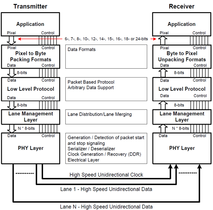 Figure 1. CSI-2 Layer2.1 Physical Layer
The physical layer is defined by the MIPI Alliance’s PHY specification. It defines the transmission medium (such as conductors), input/output circuits, and clock mechanisms to accurately capture “0” and “1”.
(1) It specifies the transmission lines, circuit parameters, clock synchronization mechanisms, etc., to ensure that data is not corrupted;
(2) It defines the “start” and “end” rules for signals to ensure orderly data transmission.
2.2 Protocol Layer
At the transmitter end, the protocol layer adds a Header and data verification information to the data.
At the receiver end, the protocol layer parses the header and then hands it over to the corresponding logic for processing while performing error detection to ensure data integrity and correctness.
(1) Pixel/Byte Packing/Unpacking Layer (Pixel/Byte Packing & Unpacking Layer)
TX: This layer’s function is to pack different pixel formats pixels (supporting 6bits-24bits) into bytes (8bits), and pass them to the next layer Low Level Protocol.
RX: It unpacks the bytes received from Low Level Protocol into pixels, passing them to the upper layer Application.
(2) Low Level Protocol (LLP)
Ensures that data is synchronized by byte and bit from SoT to EoT. The minimum transmission unit is 1Byte.
Manages the endianness.
(3) Lane Management (Lane Management Layer)
At this layer, CSI-2 is scalable (Lane-scalable), allowing the selection of the number of transmission lanes (1~4) based on bandwidth requirements.
TX: If multiple lanes are selected, the transmitter needs to allocate data to each lane for parallel transmission.
RX: Receives data from multiple lanes and restores it to the original data stream.
2.3 Application Layer
The application layer is primarily responsible for higher-level data encoding and parsing, used to process information in the data stream.
3. CCI
-
CCI (Camera Control Interface) is a dual-wire, bidirectional, half-duplex serial interface.
-
CCI is used to control the CSI-2 transmitter (camera).
-
In CSI-2, the receiver (processor) is the CCI Master, and the transmitter (camera) is the CCI Slave.
-
CCI acts as the controller for the camera, allowing the mobile phone SoC to control camera parameters, such as resolution, frame rate, exposure, etc.
-
CCI is based on I2C (Fast Mode 400KHz, 7bit address addressing), but does not support Multi-Master Mode. For example, a mobile phone with both front and rear cameras can connect both cameras (CCI slave), but only has one Master (the mobile processor).
In simple terms, CSI-2 is used to transmit photos, while CCI is used to adjust camera parameters.
4. Multi-Lane Distribution
During Multi-Lane Distribution, it may occur that the total number of bytes to be transmitted cannot be evenly divided by the number of Lane. All channels send simultaneously, so some channels may finish early. Each D-PHY data Lane operates independently, unaffected by other Lane.
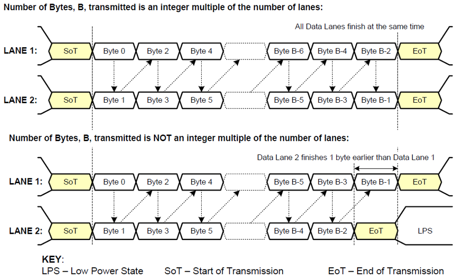 Figure 2. Two Lane Multi-Lane Example5. Low Level Protocol
LLP has two types of packets: long packets (Long Packet) and short packets (Short Packet).
At the start of each packet, the device first switches from LP mode to HS mode, and finally sends ST.
If at the end it finds the ET sequence, it returns to LP mode.
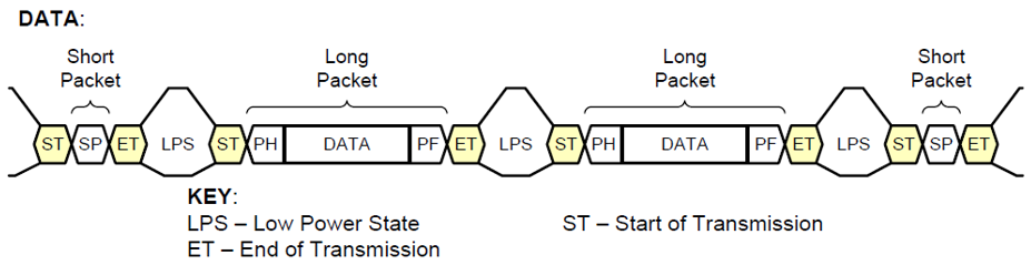 Figure 3. Low Level Protocol6. Long PacketLong Packet
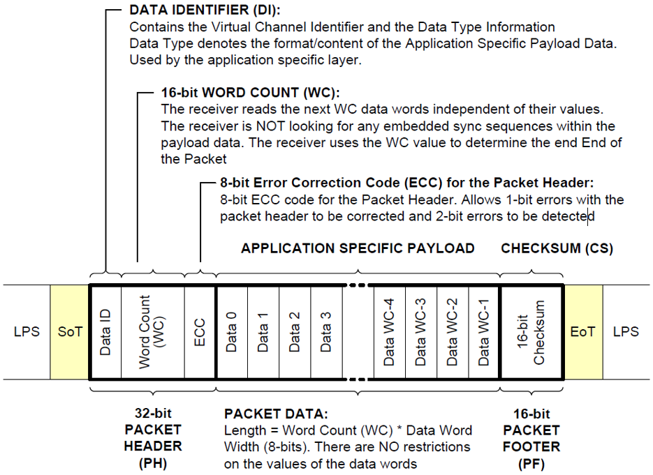
Figure 4. Long Packet Structure
From the above figure, we can see:
(1) A Long Packet consists of PH (Packet Header), Data Payload and PF (Packet Footer).
(2) PH is further composed of DI, WC, and ECC.
DI: Defines the virtual channel (Virtual Channel, VC) and data type (Date Type, DT).
WC (Word Count): Word count. After parsing the PH, the receiver will read Word Count x 8bit of data. When reading data, the synchronization code (Sync Code) will not be checked (i.e., the content can be any value).
ECC:8bit error correction code. Used to detect and correct errors in the packet header. It can correct 1-bit errors and detect 2-bit errors.
PF contains a 16bit checksum used to check whether the data packet is transmitted correctly.
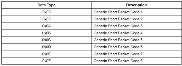
Date Type (DT): 0x10~0x37 represents different data formats, as shown in the table below:
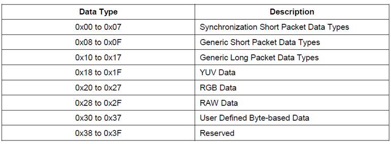
In the above table, the first 2 rows represent short packet data types, while the following 6 rows represent long packet data types.
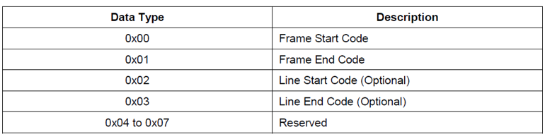
Short packet data type format is expanded as shown in the table below:
6.1 Data Transmission Order
Each byte is transmitted with the least significant bit (LSB) first.
Multi-byte data is transmitted with the least significant byte first.
6.2 Packet Parsing Process
(1) Read SoT, and perform packet parsing;
(2) Parse the Packet Header, obtaining DI, Word Count, and ECC;
(3) Based on Word Count, read Data Payload;
(4) Read the Packet Footer and check if the checksum is correct;
(5) After parsing, wait for EoT. Then continue to wait for the next SoT to process the next data packet.
7. Short PacketShort Packet
Short Packet only contains the PH header, without a footer or Data Payload. The WC field in the header will be replaced by the “short packet data field”. The header still contains 8bit ECC, which can correct 1bit errors and detect 2bit errors, ensuring data correctness.
From the following figure, it can be seen that the information capacity of the short packet is much smaller than that of the long packet, but it is critical. The functions of the short packet are as follows:
(1) Frame synchronization data type: represents the frame number (Frame Number);
(2) Line synchronization data type: represents the line number (Line Number);
(3) Generic short packet data type: user-defined, can store any content.
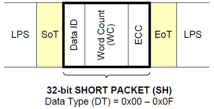 Figure 5. Short Packet Structure Data ID consists of VC and DT two parts, as shown in the following figure.VC is located in the high 2bit, while DT is in the low 6bit.
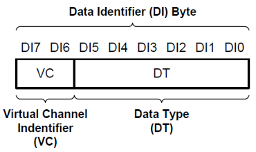 Figure 5. Data Identifier Byte
VC serves to provide multiple independent data channels within the same data stream, supporting interleaved transmission of different data streams. The receiver will detect the VC number and correctly split the interleaved video streams into the corresponding channels. Since VC 2bit, it supports a maximum of 4 independent data streams, meaning valid virtual channel numbers range from 0 to 3.
The VC identifier in peripherals should support programmable configuration, allowing the Host Processor to control the demultiplexing of data streams.
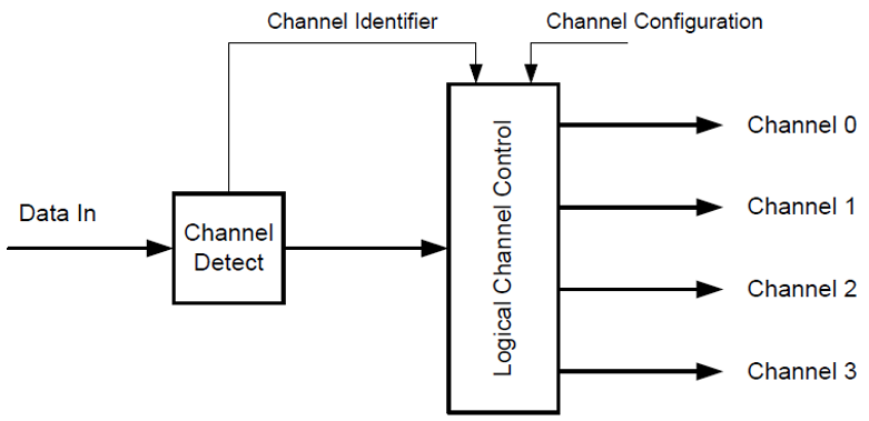
Figure 6. Logical Channel Block Diagram
7.1 General Short Packet Data Format
Transmits additional control or timing information:
(1) Controls the opening and closing of the camera shutter;
(2) Triggers the flash;
(3) Other specific application-required synchronization signals.
 Welcome to follow the WeChat public account “Chip Strategy“! In a small space, strategize; at the micro-nano scale, win thousands of miles. Here, we will share knowledge related to chip design, cutting-edge technology, and industry dynamics, looking forward to communicating and discussing with you for mutual progress!