In the vast knowledge system of embedded hardware, there are many discrete knowledge points that can easily be overlooked. Therefore, this article aims to organize these easily forgotten or misunderstood concepts for reference and learning. The focus will be on the learning of push-pull, open-drain, high-Z state, and pull-up resistors.
Basics of GPIO
The following diagram is an excerpt from the datasheet, which includes an introduction to the relevant modes of GPIO.
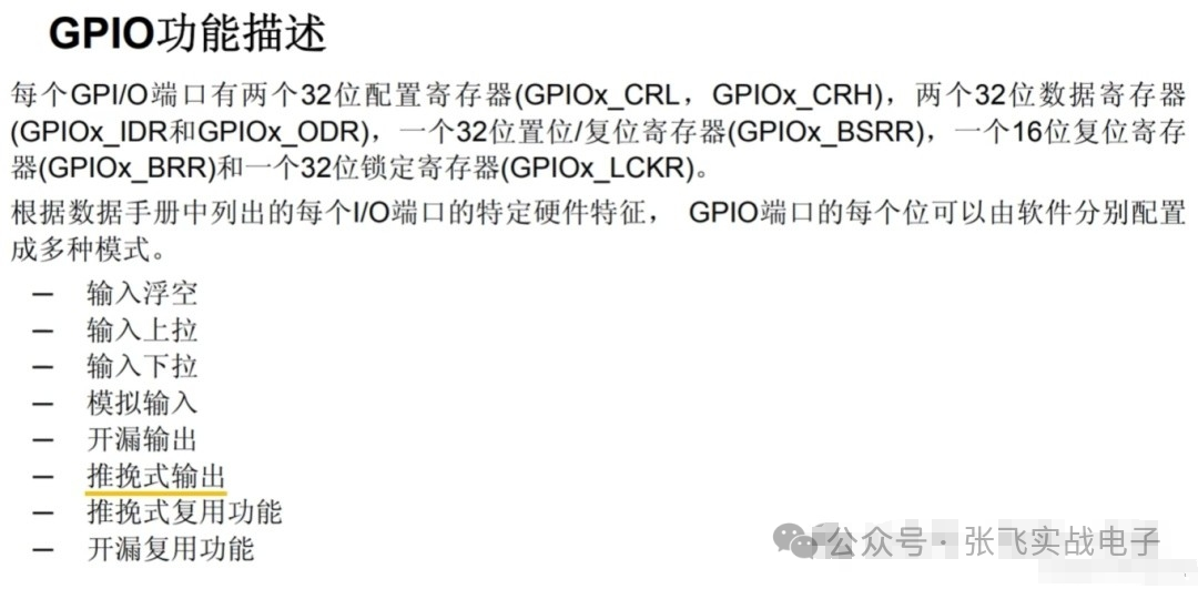
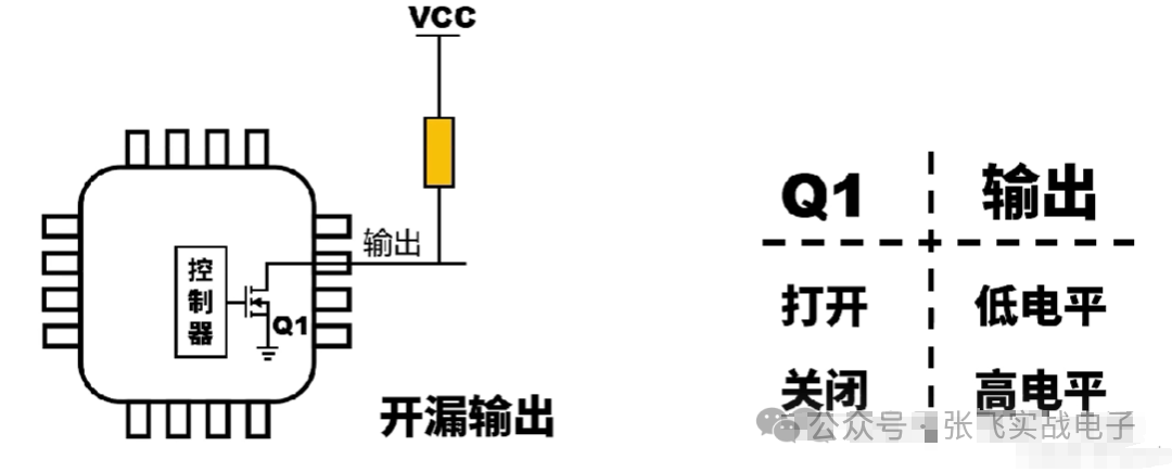
When an MCU outputs, there are two modes: one is called push-pull mode, and the other is open-drain mode. For a GPIO, it can either output a high level or a low level. Why are there these two modes? The answer will be discussed later.
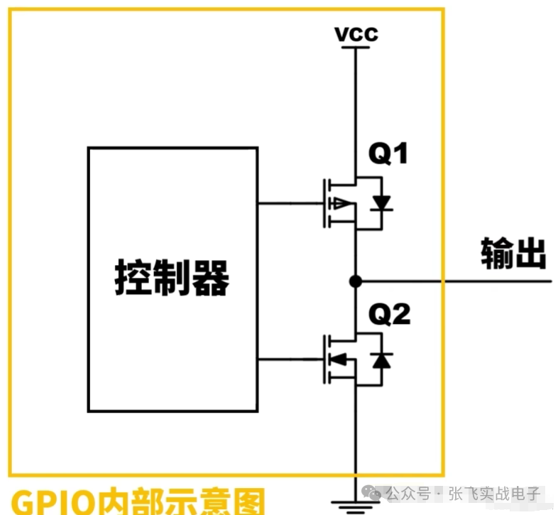
Internal Structure Diagram of GPIO
As shown in the figure below, we need to focus on the switching states of the MOSFETs, which can be enumerated into four situations as follows:
| Q1 | Q2 | OUT |
| open | close | High |
| close | open | Low |
| close | close | Floating |
| open | open | Short Circuit |
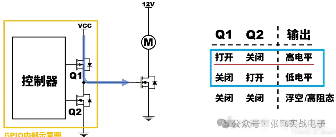
Understanding Push-Pull
When Q1 PMOS is turned on and Q2 NMOS is turned off, VCC supplies power to the gate of the NMOS in the load circuit, which pushes current out, resulting in a high output level. When Q1 PMOS is turned off and Q2 NMOS is turned on, the NMOS gate in the load circuit discharges, pulling current back. Here, NMOS is used, and the reasons for using NMOS have been discussed in the hardware section of this column, along with application scenarios. If you still do not understand, you can refer back to that section.
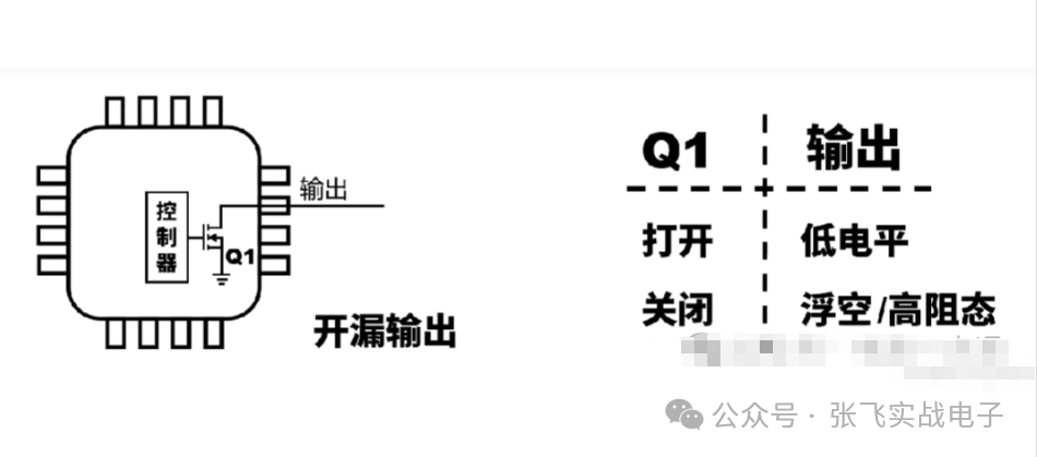
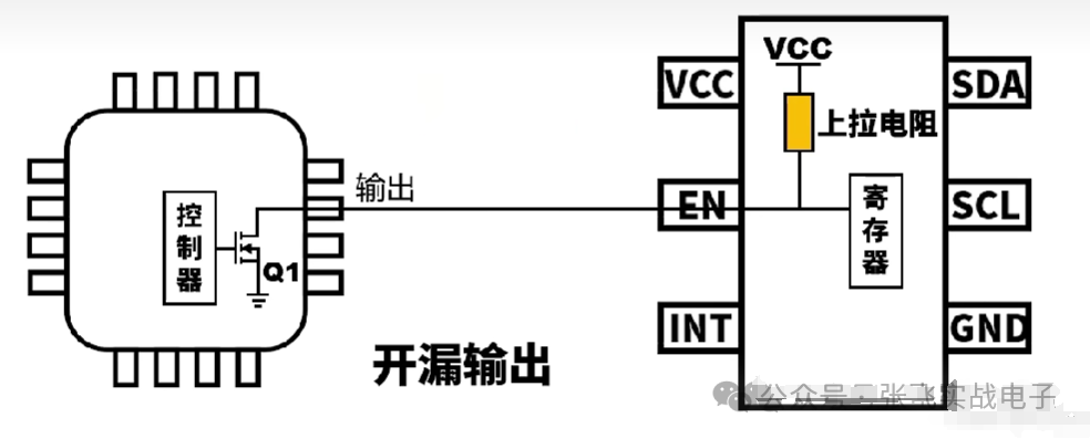
Understanding Open-Drain with Strong Drive Capability
In open-drain mode, if no external pull-up resistor is added, the situation is as shown in the figure below, which is unacceptable.
Therefore, we need to add an external resistor, a pull-up resistor.
The first function is to change the high-level voltage to prevent the main control from damaging related components. For example, in IIC, if we want the main control to control a chip, but the main control outputs a high level of 5V while the chip pin only supports 3.3V input, it could lead to the chip being burned out and other uncertain issues. Therefore, we need to use open-drain mode, and most importantly, we need to connect an external pull-up resistor to pull the 5V down to 3.3V.
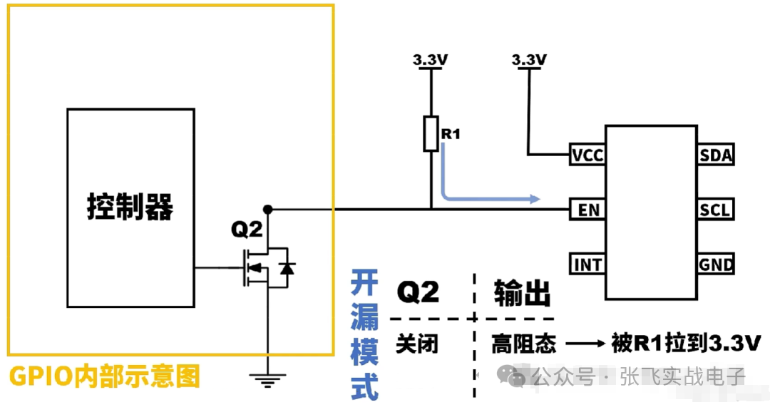
In this case, when NMOS is off, it is in a high-Z state,with the high level provided externally, and when it is on, it outputs a low level.
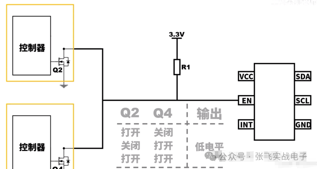
The second function is to allow multiple GPIOs to control the chip simultaneously, but push-pull would cause a short circuit.
Additionally, it is worth noting that the I2C bus can theoretically connect up to 127 devices (7-bit addressing mode), which is 2^7 (essentially, the first 7 bits are the address and the last bit is the direction) minus one device, resulting in 127.
Differences Between Push-Pull and Open-Drain
| Output State | Directly outputs high and low levels | Only outputs low level, or outputs high level through pull-up resistor |
| Driving Method | Bidirectional drive (high and low levels) | Only low level drive (high level provided externally) |
| Output Capability | High drive capability | Low drive capability (requires pull-up resistor) |
| Applicable Scenarios | General digital output, control signals | Multi-device shared bus, I2C, 1-Wire, etc. |
| Advantages | Fast response speed, can provide large current | Supports multi-device sharing, avoids drive conflicts |
| Disadvantages | Not suitable for multiple devices sharing, higher power consumption | Requires external pull-up resistor, slower response speed |
What Does the Pull-Up Resistor Pull Up?
Application Scenarios of Pull-Up Resistors
Pull-up resistors are always associated with the appearance of MOSFETs, which actually work in open-drain mode for GPIO ports.
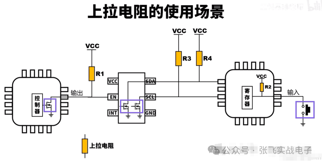
However, if the relevant external chip integrates a pull-up resistor, we do not need to add one externally, as shown in the figure below:
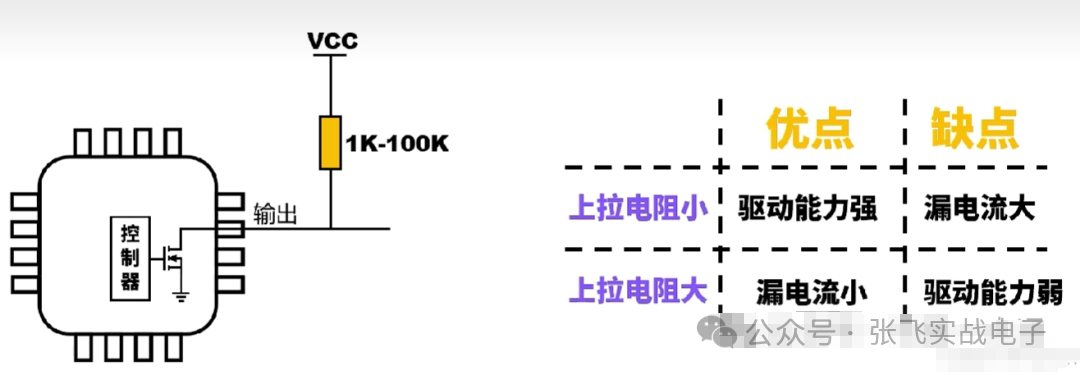
How to Choose the Value of Pull-Up Resistors?
The vast majority of pull-up resistors are between 1K and 100K. A smaller resistor has the advantage of strong drive capability, while a larger resistor has a smaller leakage current.

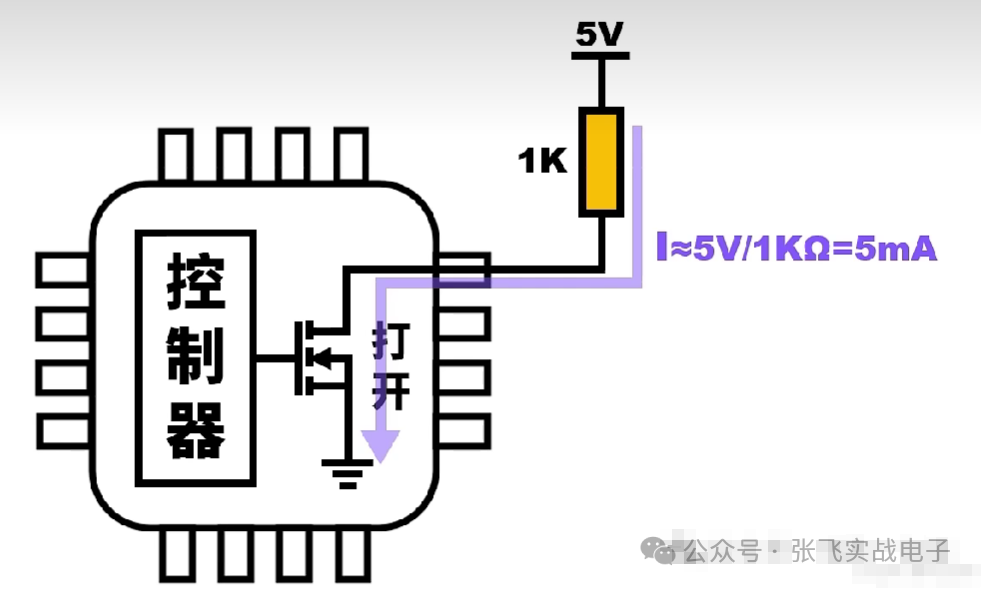
What is Leakage Current? What is Drive Capability?
Leakage current occurs when the MOSFET is turned on, creating a pathway. If this resistor is 1K, the leakage current would be 5mA, which is wasted current and can generate heat. Therefore, a larger resistance value is better, but the drive capability will be weaker.
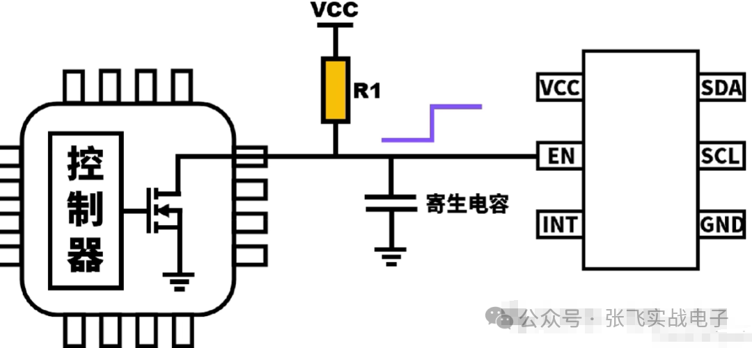
What is Drive Capability?
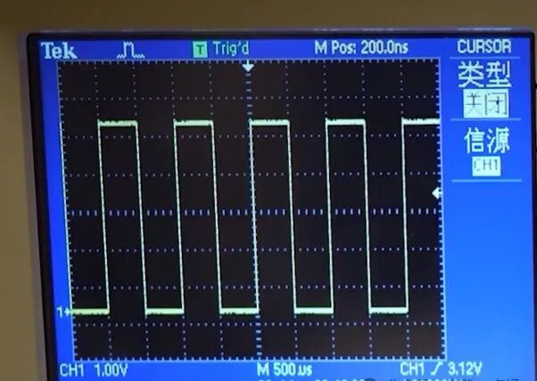
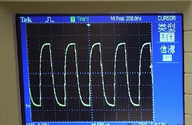
It refers to the process of transitioning from low level to high level. Although you see a momentary rising edge, the transition from low to high is not instantaneous when the scale is enlarged. This is the rise time discussed in previous chapters. It also needs to be combined with the hardware selection of the relevant chip load; otherwise, distortion may occur.
— END —
Disclaimer: This article is reprinted from the internet,and the copyright belongs to the original author. If there are any copyright issues, please contact us in a timely manner. Thank you!
Join the Fan Group
Zhang Fei Practical Electronics has opened a dedicated learning group for fans of the public account. Students who want to join the group for learning discussions or to receive document materials can scan the operational QR code in the image to join easily!
(Advertisements and peers, please do not enter)