 Search WeChat
 Technical Training
For beginners in PLC ladder diagram programming, it’s essential to follow certain rules and develop good habits.
Below, using the Mitsubishi FX series PLC as an example, I will briefly introduce the rules that need to be followed when programming PLC ladder diagrams, hoping to help everyone. It should be noted that although this article uses Mitsubishi PLC as an example, these rules can also be adhered to when programming other PLCs.
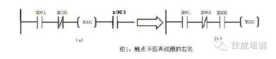
1. Ladder rungs always start with a horizontal line and end with a vertical line (usually the horizontal line can be omitted, only the left bus bar is drawn). The left side of each rung is the contact combination indicating the conditions for driving the logic coil, while the logic coil indicating the result can only connect to the right bus bar. Contacts cannot appear on the right side of the coil. As shown in the figure, (a) should be changed to (b):
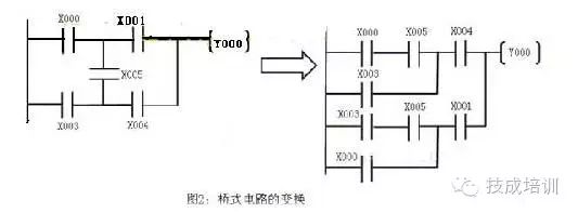
2. Contacts should be drawn on the horizontal line, not on the vertical line, as shown in the figure (a), where the contact X005 and other contacts cannot be identified. For such bridge circuits, all pathways should be drawn separately according to the principle of unidirectionality from left to right and from top to bottom. As shown in figure (b):
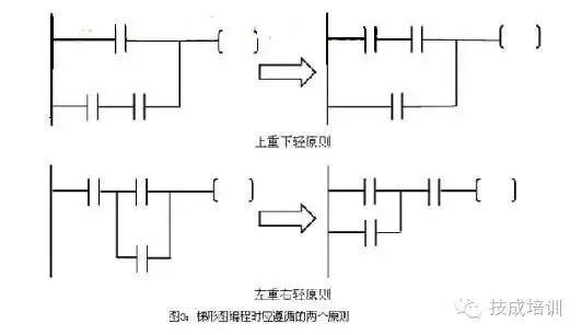
3. When connecting parallel blocks in series, the pathways with more contacts should be placed on the left side of the ladder diagram (the principle of left-heavy and right-light); when connecting series blocks in parallel, the pathways with more parallel contacts should be placed on the upper part of the ladder diagram (the principle of top-heavy and bottom-light). This makes the program concise and reduces the instruction scanning time, which is particularly important for large programs. As shown in the figure:
4. Avoid using dual-coil outputs. If the same coil of the same component is used two times or more in the same ladder diagram, it is called dual-coil output or repeated use of coils. Dual-coil output is one of the common mistakes made by beginners in ladder diagrams. In dual-coil output, only the last coil is effective, while the previous coils are ineffective. This is determined by the scanning characteristics of the PLC.
The PLC’s CPU adopts a cyclic scanning operation method. It usually includes five periods (as shown in the figure): internal diagnosis and processing, communication with external devices, input sampling, user program execution, and output refresh. When the method switch is in STOP, only the first two periods are executed: internal diagnosis and processing, and communication with external devices.
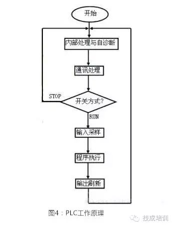
1. Input sampling period
The PLC sequentially reads the status of each input terminal and stores it in what we call the input image register. When entering the program execution period, if the input terminal status changes, the corresponding cell information in the input image area will not change until the next scanning cycle’s input sampling period. Therefore, the PLC will ignore pulse changes in the input terminal less than the scanning cycle.
2. Program execution period
The PLC scans the user program starting from step 0, in the order of top to bottom, left to right, and performs logical operations. The PLC performs logical operations based on the contents of the input image area and writes the results into the output image area, rather than directly outputting to the terminals.
3. Output refresh period
The PLC changes the status of the output terminals based on the contents of the output image area. This is the actual output of the PLC.
Above, I briefly explained the working principle of the PLC. Next, we will illustrate why it is not advisable to reuse coils when writing ladder diagram programs.
As shown in the figure, suppose during the input sampling, the input image area has X001=ON, X002=OFF, Y003=ON, Y004=ON written into the output image area. However, continuing to execute, since X002=OFF, Y003=OFF, this latter result is also written into the output image area, changing the original status of Y003.
Thus, during the output refresh period, the actual external output is Y003=OFF, Y004=ON. Many beginners encounter the question of why Y003 does not output when X001 is already closed. The logical relationship is incorrect. This is actually due to the use of dual coils.
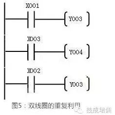
Note: What we say is that it is not advisable (preferably not) to use dual coils; dual coils are not absolutely prohibited, and in some special cases, dual coils can also be used, but this requires you to have rich programming experience and skills.
Next, we will discuss this point. However, for beginners, it is still best to avoid taking this risk.
In fact, from the above example, it can be seen that the reason for the chaotic output of Y003 due to the reuse of coils is due to the sequential execution of the program from top to bottom.
However, if we can change the order of program execution, ensuring that at any time only one logic drive occurs for two coils, dual coils can be used. The most common method is to use jump instructions. As shown in the figure:
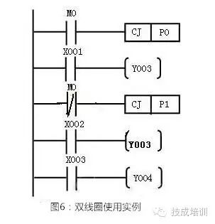
Program Analysis:M0 is closed, the program jumps to P0 (not executing the X001 statement), M0 normally closed is disconnected, CJP1 will not occur, and the next statement is executed. At this time, Y003 will drive the status of X002. When M0 is disconnected, the program executes in order and drives T003 based on the status of X001. When M0 is normally closed, it jumps to P1 to drive Y004 based on the status of X003, thus skipping the statement that drives Y003 with X002. It can be seen that at the same time, only one drive for Y003 can occur. At this time, dual coil usage is possible.
However, when programming ladder diagrams, we should still try to avoid using dual coils, and introducing auxiliary relays is a common method. As shown in the figure:
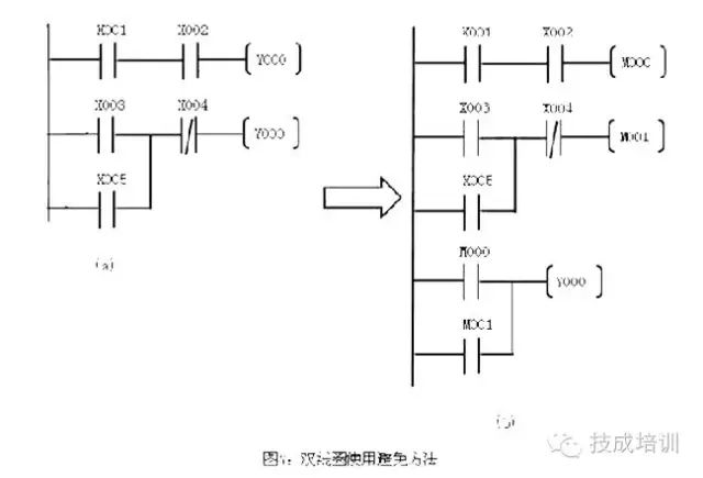
In figure (b), the contacts X001 and X002 control the auxiliary relay M000, contacts X003~X005 control the auxiliary relay M001, and then the parallel combination of the two relays M000 and M001 controls the coil Y000. Thus, the logical relationship remains unchanged, but the dual coil becomes a single coil.

Disclaimer: This article is reprinted from the internet, and the copyright belongs to the original author. If there are any copyright issues, please contact us in time to delete it. Thank you!HISTORY/Previous Recommendations
Complete question bank for the 2022 Electrical Worker Beginner Exam (including answers)
3 essential tools for electrical workers, can be easily opened with WeChat!
[Collection] The “path” of a ten-year electrician, the secret to earning over ten thousand a month!
Five major electrical drawing software (CAD, Eplan, CADe_simu…), which one do you pick?
Latest electrical CAD drawing software, with super detailed installation tutorial!
Latest electrical drawing software EPLAN, with super detailed installation tutorial!
Common problems for beginners using S7-200 SMART programming software (with download link)
Comprehensive electrical calculation EXCEL table, automatically generated! Electrical calculations without asking for help!
Bluetooth headphones, introductory books for electricians/PLC are available for free? Come and get your electrical gifts!
Basic skills in PLC programming: ladder diagrams and control circuits (with 1164 practical cases of Mitsubishi PLC)
Still can’t understand electrical diagrams? Basics of electrician diagram recognition, simulation software available, quickly get started with theory and practice!
12 free electrical videos, 10GB software/e-book resources, and 30 days of free electrical live classes are being given away!
Don’t forget to like + check it out!
 Click “Read the original text” to learn PLC/electrician courses for free!