
1. Ladder Diagram (LAD) Ladder Diagram language is derived from the commonly used relay and contactor logical control, simplifying the evolution of symbols. It is intuitive, practical, and easily accepted by electrical technicians, making it the most widely used programming language for PLCs today. In a PLC program diagram, the left and right buses are similar to the power lines controlled by relays and contactors, the output coils are similar to loads, and the input contacts are similar to buttons. The ladder diagram consists of several rungs arranged from top to bottom, each starting at the left bus, passing through contacts and coils, and ending at the right bus. Figure 1 shows a typical program written in Ladder Diagram language.
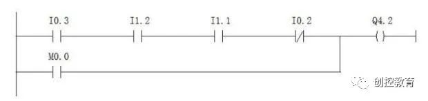
Figure 1 Ladder Diagram Language
In the above diagram, the “normally open contacts” I0.3, I1.2, I1.1 and the “normally closed contact” I0.2 are connected in series and then paralleled with the “normally open contact” M0.0, supplying power to the “coil” Q4.2. In a relay and contactor-type circuit, programming with Ladder Diagram is very clear, just like viewing an electrical connection diagram.
2. Function Block Diagram (FBD) FBD represents control logic in the form of block diagrams, similar to programming languages for digital logic gates. During university, I had a strong interest in digital circuits, leading to a natural preference for FBD language later on, and I tend to use FBD for programming at work. FBD language is easy to master for those with a background in digital circuits; it represents logical operations using blocks similar to AND gates and OR gates, where the left side of the block contains input variables and the right side contains output variables. Signals flow from left to right, and various functional blocks can be connected in series or have intermediate signals inserted. The number of combinational logic operation blocks before each final output is limited, and the number of output results for the same group of logical operations may vary depending on the operating system. With extensions, it can represent not only various simple logical operations but also complex operations and functions. The control logic of the Ladder Diagram in Figure 1 can be programmed using FBD as shown in Figure 2.
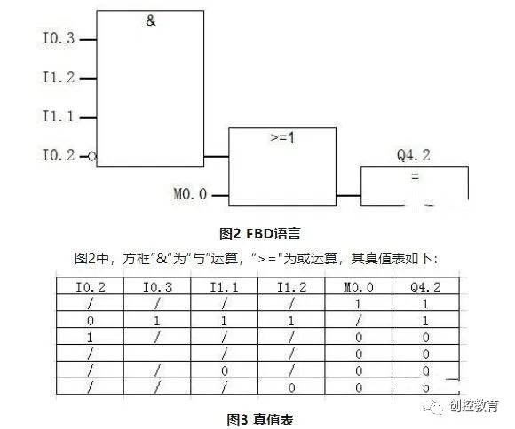
The programming process of FBD language is similar to building a circuit using integrated modules in digital circuits, where each module has its own function. According to control needs, the appropriate modules are selected and connected with “wires”.
3. Statement List (STL) STL is a mnemonic programming language similar to assembly language, using one or several easily remembered characters to represent a certain operational function of the PLC. Each statement consists of three parts: address (step number), opcode (instruction), and operand (data). The statement list can accomplish certain functions that are not easily implemented with Ladder Diagram or Function Block Diagram. Friends who have worked with microcontrollers may have an advantage when learning STL. Figure 4 shows the program for the same control logic written in STL.
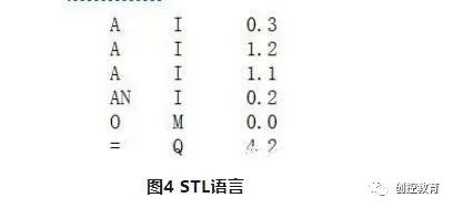
In this, “A” represents AND operation, “AN” represents NAND operation, “O” represents OR operation, and “=” represents assignment operation. Programming in STL requires a considerable understanding of the PLC’s micro-logical structure, such as various storage modes, familiarity with various addressing methods, and proficiency in various programming mnemonics. It can be said that those who can proficiently use STL programming are quite adept at Siemens PLCs. My STL programming is still at the beginner stage; I recall writing an interface program for a photoelectric distance meter using STL last year, which took a toll on my brain cells and is truly a painful memory.
4. How to Choose Among the Three Languages?
1. Mutual Conversion of the Three LanguagesIn STEP7, you can select from the menu to switch between the three languages. As shown in Figure 5.
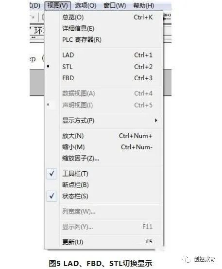
Of course, LAD and FBD can usually be switched directly, and LAD and FBD can also be converted to STL language, but STL cannot necessarily be converted back to LAD or FBD.
2. Comparison of Advantages and Disadvantages of the Three Languages LAD is the most commonly used PLC programming language; it is intuitive and visual, and anyone with a basic understanding of electricity can quickly get started. Moreover, almost all PLCs on the market support LAD programming, making it universally applicable. It performs well in relay or contactor-type logical functions, but as more program function units are integrated into STEP7, the programs written in LAD sometimes appear a bit “awkward”. As shown in Figure 6, the program unit “CMP>=D” appears as a “block” in FBD, along with other units; however, in LAD, it still appears as a “block” and looks somewhat out of place among other “contact units”, although it does not affect logic, it appears untidy.
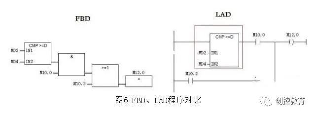
FBD language programs, in my opinion, have a stronger logic. During the programming process, based on the control logic of the object being controlled, it is much easier to clarify the program logic, making programming significantly easier. Meanwhile, STEP7 provides a large number of functional “program logic units” that can be implemented simply by dragging and dropping. STL is close to assembly language, has a higher entry point, and is not easy to master. However, in situations where hardware manipulation is required, such as the interface program for the laser distance meter I once wrote, STL language must be used.
(Content sourced from the internet, copyright belongs to the original author)Disclaimer: If copyright issues arise, please contact for deletion!No individual or institution assumes related legal responsibilities.