Introduction
With the widespread application of Type-C interfaces in electronic devices, the accuracy of the cable wiring sequence directly determines the device’s power supply, data transmission, and functional expansion capabilities. Only cables with a complete wiring sequence can meet the demands of high-speed data transmission. Cables lacking wire cores cannot support Thunderbolt and high-speed USB data transmission.
The POWER-Z CT001 Type-C cable tester, as a portable and precise testing tool, is designed based on the standard pin definitions of the Type-C interface, allowing for quick verification of cable continuity and wiring sequence. The reserved test pads, combined with a multimeter, can further accurately locate the function of each wire core corresponding to the pin, providing an efficient solution for cable quality testing and troubleshooting.
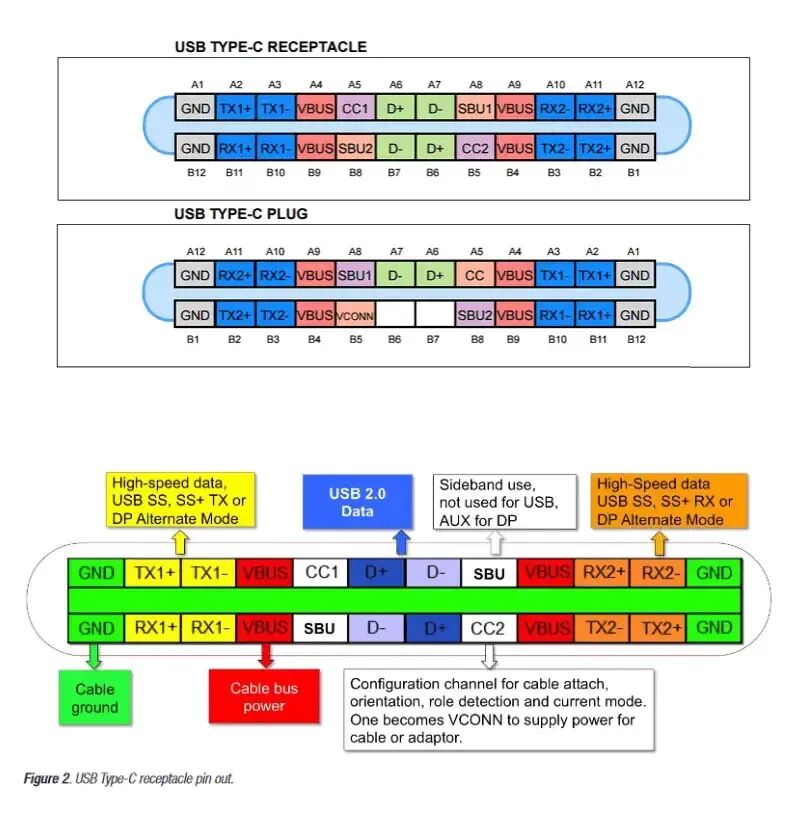
A brief introduction to the Type-C interface definition:
The Type-C interface is divided into a receptacle (female) and a plug (male). The complete Type-C pin configuration consists of 24 pins, with the definitions of each pin as follows:
1. VBUS: Four pins for the bus voltage supply between devices, providing power regardless of the orientation;
2. GND: Four pins for the power return circuit between devices, also providing a return circuit regardless of the orientation;
3. TX+/TX- and RX+/RX-: Four pairs for USB 3.0 high-speed signals;
4. D+/D-: Two pairs for USB 2.0 signals. At the receptacle, these two pairs will short-circuit into one pair;
5. CC/CONN: The CC pin is a configuration pin used to detect device connection and orientation, and is also the line for USB PD communication: VCONN is the pin diagonally opposite the CC pin; when one pin is confirmed as CC, the other is defined as VCONN, used to power eMark cables.
6. SBU1/SBU2: Multipurpose pins, used for transmitting auxiliary functions, such as audio, video, etc.
The receptacle has 24 pins, with the upper and lower pins being diagonally symmetrical to meet user needs for reversible insertion; the plug has 22 pins, retaining only one pair of D+/D- pins due to the USB 2.0 specification.
Testing the cable wiring sequence with POWER-Z CT001 and a multimeter
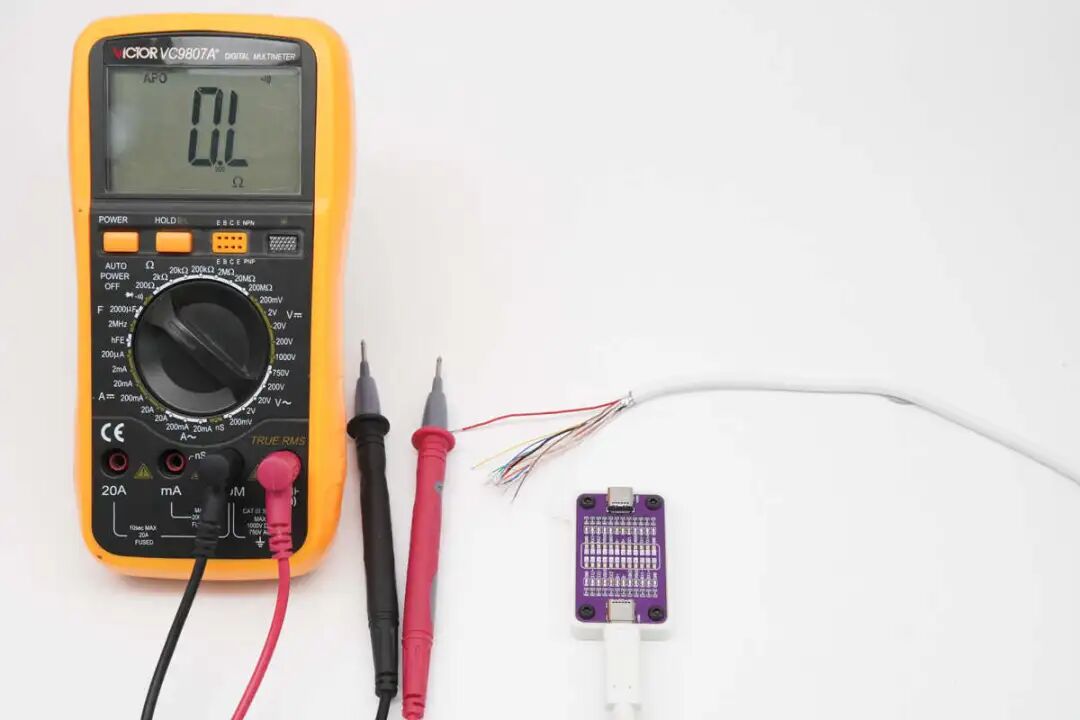
Set the multimeter to the buzzer mode, and connect one end of the cable to the USB-C2 port of the POWER-Z CT001..
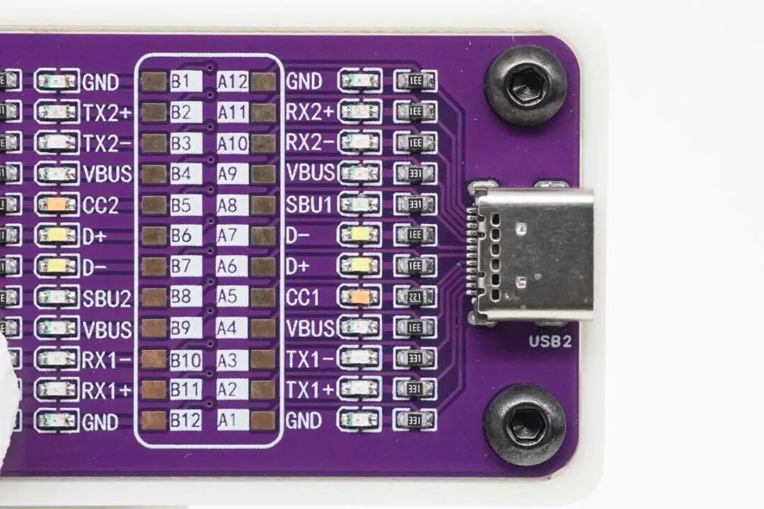
The USB-C2 port of the POWER-Z CT001 is labeled “USB2” below the Type-C interface for easy identification of the test port.
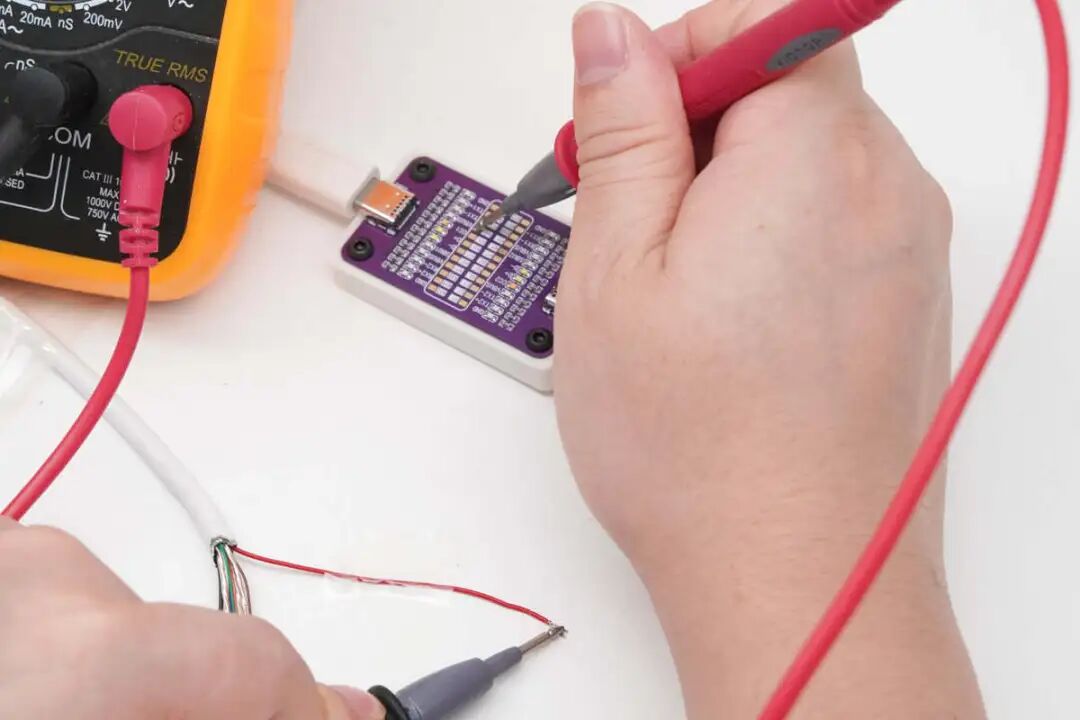
Using the black probe (black lead) of the multimeter, connect it to the wire to be tested, while the other red probe (red lead) is sequentially touched to the copper pieces corresponding to pins 24 until the buzzer sounds, indicating the corresponding Type-C interface pin.
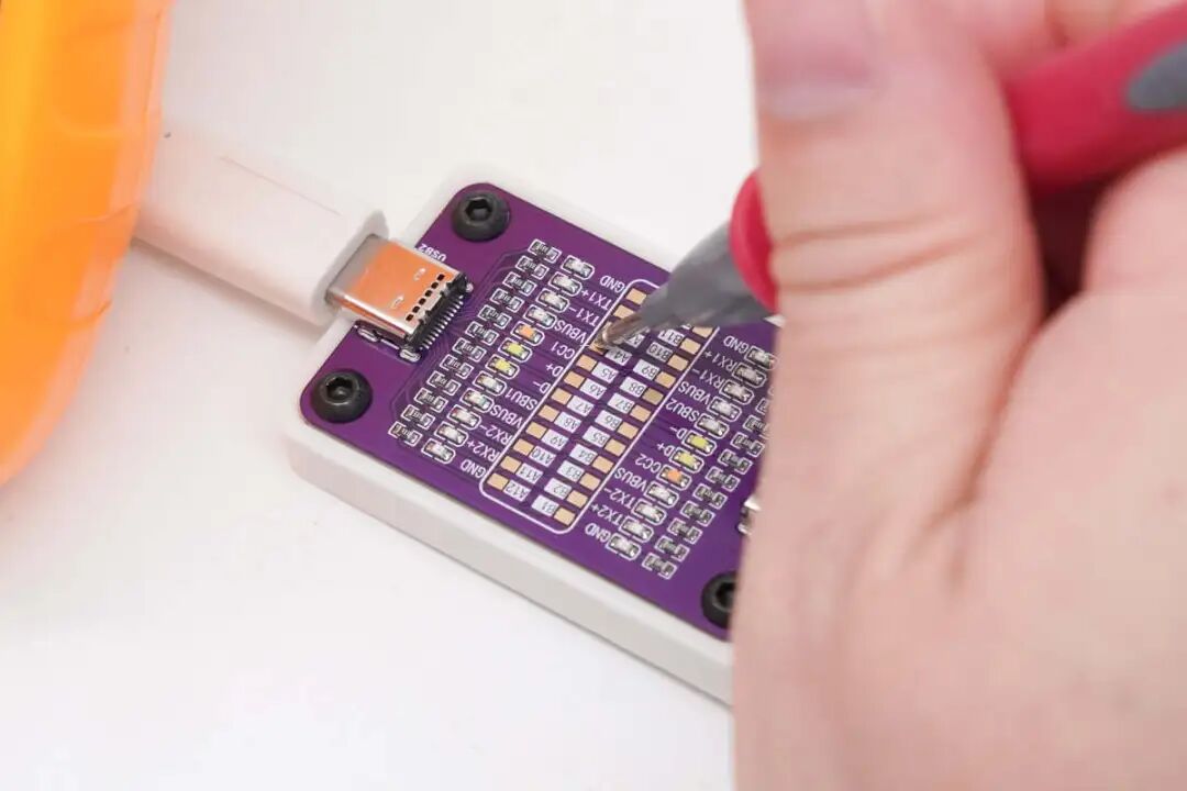
After testing, when the red probe touches the VBUS pin, the buzzer sounds, indicating that the red wire core of this data cable corresponds to the VBUS pin.
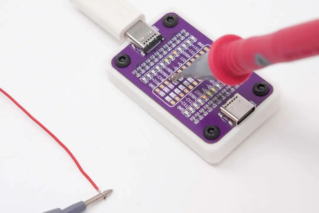
Since there are four VBUS pins, they are internally shorted in the USB-C plug. The VBUS voltage pins provide power regardless of the orientation; any of the four pins can trigger the buzzer.
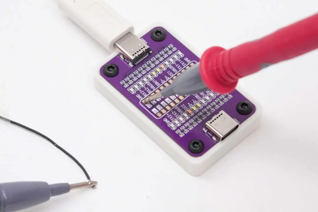
After testing, when the probe touches the GND pin, the buzzer sounds, indicating that the black wire core of this data cable corresponds to the GND pin. Similarly, since this pin has four paths providing a return circuit for power between devices, any of the GND pins can also form a connection regardless of the orientation.
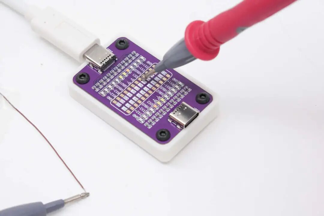
After testing, when the red probe touches the CC1 pin, the buzzer sounds, indicating that the brown wire core of this data cable corresponds to the CC1 pin.
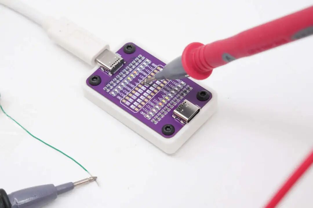
After testing, when the red probe touches the D+ pin, the buzzer sounds, indicating that the green wire core of this data cable corresponds to the D+ pin.
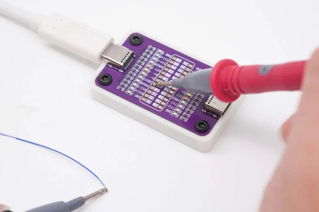
After testing, when the red probe touches the SBU1 pin, the buzzer sounds, indicating that the blue wire core of this data cable corresponds to the SBU1 pin.
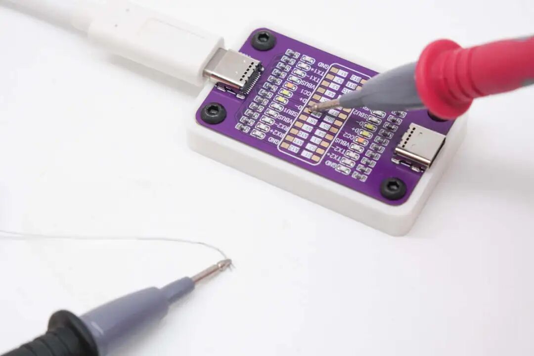
After testing, when the red probe touches the D- pin, the buzzer sounds, indicating that the white wire core of this data cable corresponds to the D- pin.
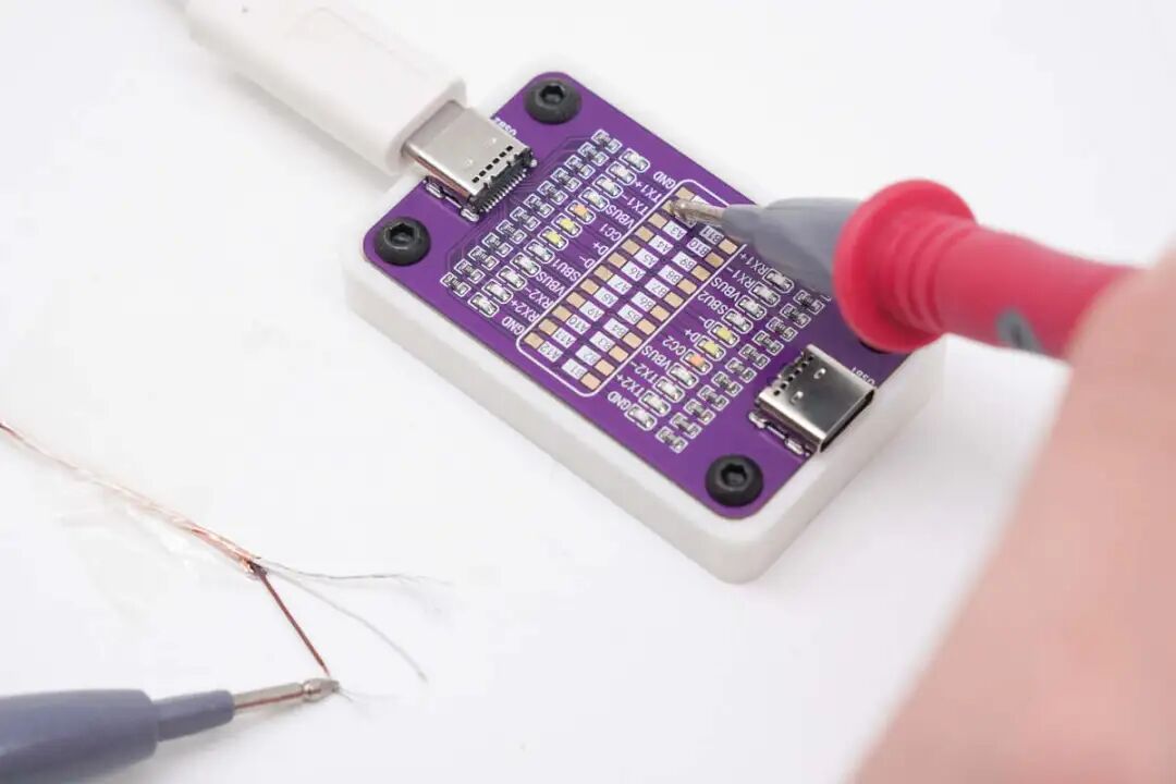
After testing, when the red probe touches the TX1+ pin, the buzzer sounds, indicating that the brown wire core inside this cable corresponds to the TX1+ pin.
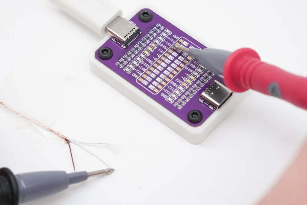
After testing, when the red probe touches the TX1- pin, the buzzer sounds, indicating that the white wire core inside this cable corresponds to the TX1- pin.
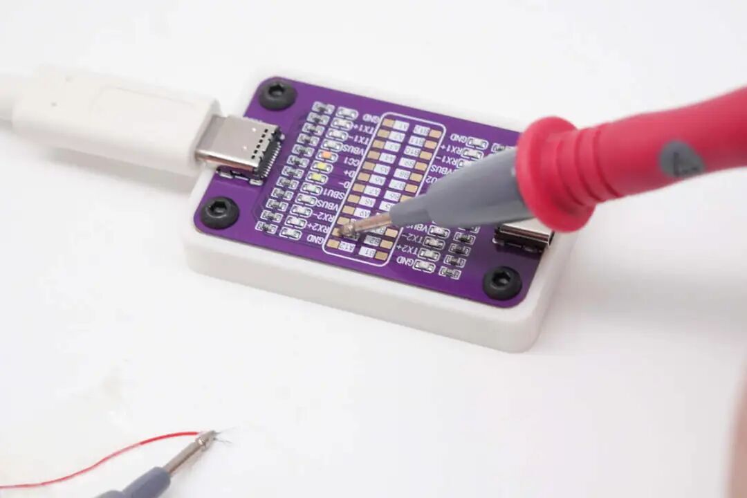
After testing, when the red probe touches the RX2+ pin, the buzzer sounds, indicating that the small red wire core of this data cable corresponds to the RX2+ pin.
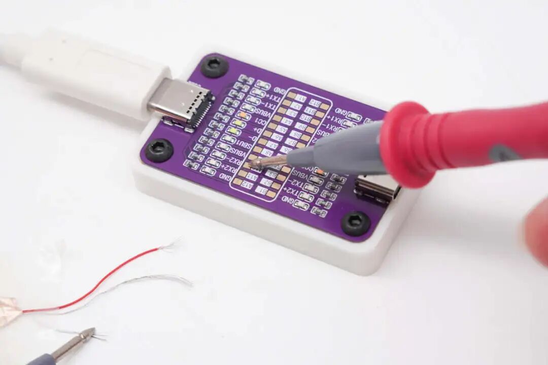
After testing, when the red probe touches the RX2- pin, the buzzer sounds, indicating that the white wire core inside this cable corresponds to the RX2- pin.
Conclusion
The POWER-Z CT001, using the buzzer function of the multimeter, can determine the connectivity status of the wiring sequence pins (single-sided 12-pin detection). When one end of the Type-C cable is connected to a port on the POWER-Z CT001 with the battery removed, the red and black probes of the multimeter can be tested one by one, and by observing the buzzer’s response, the function of the corresponding wire core can be determined.
Related Reading
1. New arrivals in the store: Dual-head Type-C fast charging cable testing board
2. POWER-Z CT001 Type-C cable tester function demonstration
3. POWER-Z new official website launched, upgraded experience set sail
4. How to use POWER-Z KM003C to test PD3.2 AVS protocol
5. From protocol deception to automated testing, POWER-Z launches five products supporting PD 3.1 240W fast charging power testing


 Click to read the original text