In this article, we add a periodic Timer to the PCIe device previously simulated in Qemu. Once this Timer is enabled, it will trigger an MSI interrupt to the Qemu virtual machine every second. To verify that this interrupt function works correctly, we need to add interrupt handling capabilities to the driver for this PCIe device. This article will introduce how to register interrupts in a WDF driver and handle them.In a WDF driver, the WDF API function WdfInterruptCreate is typically used in the driver’s callback function EvtDriverDeviceAdd to create the driver object. For our PCI driver, we need to call WdfInterruptCreate to create an interrupt object for the device object after creating it in the function PciTestDriverCreateDevice. Similar to creating other WDF objects, creating an interrupt object first requires initializing a configuration structure for the interrupt object, which is the structure WDF_INTERRUPT_CONFIG. Like other WDF object configuration structures, the interrupt object’s configuration structure also has some callback functions that the driver needs to implement.The most important callback function on the WDF_INTERRUPT_CONFIG structure is EvtInterruptIsr, which is the interrupt handling function. Additionally, there are two other callbacks: EvtWdfInterruptEnable and EvtWdfInterruptDisable. The EvtWdfInterruptEnable function is called when the WDF driver framework puts the device into D0 state, while EvtWdfInterruptDisable is called when the WDF driver framework puts the device into D3 state. The implementation of these two functions is straightforward (our PCIe device does not require interrupt Enable/Disable), simply logging a message. After initializing the WDF_INTERRUPT_CONFIG, we can call WdfInterruptCreate to create the interrupt object.Actually, the WdfInterruptCreate function can also be called in the WDF driver’s callback function EvtDevicePrepareHardware, but it is a bit more complicated as it requires specifying the interrupt resource descriptor on the WDF_INTERRUPT_CONFIG structure. Therefore, we generally create the interrupt object in the callback function EvtDriverDeviceAdd. It is important to note that when creating the interrupt object in EvtDriverDeviceAdd, the Windows kernel (specifically, the PnP Manager) has not yet allocated interrupt resources for this device. After the Windows kernel allocates interrupt resources for this device, the WDF framework will fill the interrupt resources into this “pre-created” interrupt object.The so-called interrupt resources here specifically refer to MSI interrupt resources, as our PCIe device implemented in Qemu only has one MSI interrupt.Next, let’s look at the implementation of the interrupt handling function EvtInterruptIsr. The parameter Interrupt is the WDF handle of this interrupt object, and the parameter MessageID is always 0 for non-MSI interrupts. For MSI interrupts, it is the unique identifier of the MSI interrupt message. For devices with multiple MSI interrupts, this parameter is the sequence number of the MSI interrupt message within that device. Since our PCIe device only has one MSI interrupt, this parameter’s value should be 0. In the interrupt handling function, we can use WdfInterruptGetDevice to get the handle of the WDF device object to which this interrupt object belongs, and then obtain the device context structure DEVICE_CONTEXT from the device object handle. Once we have the device context structure, we can retrieve the MMIO register’s (previously mapped) virtual base address and read the Timer’s count register REG_COUNTER. We can also use the function WdfInterruptGetInfo to get some information about this interrupt object, such as: IRQ Level, whether it is a Message-signaled interrupt (MSI). Finally, it is important to note that the return value of the EvtInterruptIsr function indicates whether this interrupt has been handled. If the interrupt has been handled, it should return TRUE; if the interrupt has not been handled (for example, this is an interrupt shared by multiple devices, and this interrupt does not belong to the current device, which can be determined by checking the device’s internal interrupt status register), it should return FALSE. The WDF framework will continue to call the interrupt handling functions of other devices sharing this interrupt.At this point, you can see that the process of registering and handling interrupts in a WDF driver does not involve specific interrupt types. Whether it is an MSI interrupt or a traditional line-based interrupt (Line-Based IRQ, Pin-Based IRQ), this process can be used. The specific interrupt type is essentially transparent to the device driver, and there is no need to pay too much attention to it. This is one of the benefits of the operating system driver framework, which can shield the differences in handling different interrupt types from the specific device driver.After modifying the driver, we need to write a test program to enable this Timer, as shown in the code below. The core code of the test program is the part highlighted in red. First, we enable this Timer, and then read the Timer’s count value every second. When the read count value is not less than 10, we stop the Timer, and finally read the Timer’s count value again to check if it has been reset to zero. The following animated image shows the effect of running the Timer test program. You can see that the Timer count value increases each time it is read, and after stopping the Timer, the read count value is 0, which is consistent with our implementation logic in Qemu.
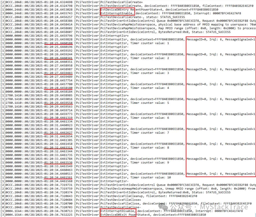
 Below is the log output from the driver during the test. Since the Timer’s interrupt occurs once per second, the driver’s interrupt handling function is called every second. The timestamps in the log also show that it is called every second, and the Timer’s count value obtained in the interrupt handling function is increasing each time. From the information obtained about the interrupt object, we can see that the interrupt’s MessageID is 0, Irql is 6 (which belongs to Device IRQL, DIRQL), and MessageSignaled is 1, indicating that this is indeed an MSI interrupt. Additionally, our provided EvtInterruptEnable and EvtInterruptDisable functions are indeed called when the device enters D0 state and exits D0 state, respectively.