In the previous article (Implementing a PCIe Device in Qemu: Adding a Periodic Timer to the Device), we introduced how to add a Timer to a PCIe device simulated by Qemu. This Timer has a counter that increments by 1 every second once enabled, and it also sends an interrupt to the virtual machine.To test the functionality of this Timer , we need to add code to control this Timer in the previously written PCI driver. There are two main tasks: first, register an interrupt handler in this PCI driver to test the periodic interrupt functionality of the Timer; second, add code to control the start and stop functionality of the Timer and read the Timer counter value to test the counting functionality. The second task involves reading and writing MMIO registers. Since we have already implemented mapping MMIO to user space, allowing direct read and write access to registers from user space, I plan to write a test application in user space to verify this.
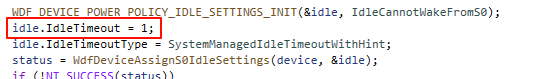
The flow of this test application for the Timer is as follows: first, open the PCIe device file to obtain a handle, then use IOCTL to map the device’s MMIO registers to the user space address space, allowing the test program to directly read and write the device’s MMIO registers in user space. Next, the program writes 1 to the REG_ENABLE_TIMER register to enable the Timer, and then the program will read the Timer counter value register REG_COUNTER every second (since the Timer increments the counter by 1 every second). This approach seems fine for writing the test program, but in practice, it can lead to the device being idle for longer than the maximum idle time set in the PCI driver, which is defined by the WDF driver framework to bring the device into D3 state: 1 ms, so it is possible that while we are accessing the PCIe device’s registers in user space, the device enters D3 state, and we can no longer read valid values from the registers.
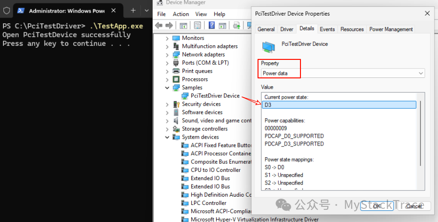
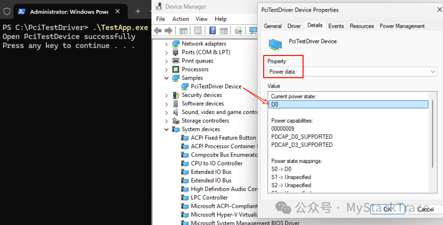
Some may wonder that when accessing the registers, we must open the device file to obtain a handle and then send IOCTL requests to the driver. Since we hold the handle to this device file, why does the device still enter D3 state? The reason is that we have set the S0 Idle Setting for this PCIe device, and even if the application holds the handle to the device file, as long as the device remains idle (for example, not interacting with the application) for longer than the set value, the WDF driver framework will still place the device into D3 low power state. The following image shows that after the application opens the device file and obtains the handle, the program executes the “pause” command to halt (without terminating), and then we check the Power data of the PCIe device in the device manager, finding that the device is in D3 state.
Is there a way to solve this problem? Of course, there is. The simplest way is to delete the above code, which will keep the device in D0 state, but this is somewhat crude and generally not recommended. We can think of another approach: can we actively notify the WDF driver framework that we need to use this device and not to place it in D3 state? After we finish using the device, we can then notify the WDF driver framework to place the device in D3 state. In fact, the WDF driver framework supports this functionality, which can be achieved through the following two functions.
WdfDeviceStopIdle: Notifies the WDF driver framework that the specified device must be placed in D0 state.
WdfDeviceResumeIdle: Notifies the WDF driver framework that the specified device is no longer needed, and if the device has been idle, it can be placed in D3 state.
With these two functions, it becomes straightforward. We just need to call the WdfDeviceStopIdle function when opening the PCIe device file to notify the WDF driver framework to place the device in D0 operational state, and when closing the PCIe device file, call the WdfDeviceResumeIdle function to notify the WDF driver that we are done with the device, and if the device remains idle, it can be placed in D3 low power mode.
Now another question arises: how does the PCIe driver know when the application opens or closes the device file? This can also be resolved. The WDF driver framework supports specifying a file object configuration for this device when creating the WDF device object, which can set up callback functions corresponding to opening and closing the device file. Through these two Callback functions, the driver can know when the application opens or closes the device file.
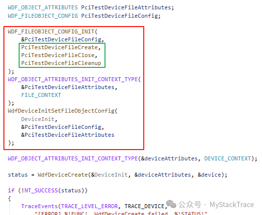
It seems that all the issues have been resolved, so let’s start writing code. First, before creating the WDF device object, we specify the WDF_FILEOBJECT_CONFIG for this device and implement the three callback functions on this structure: FileCreate, FileClose, and FileCleanup. The focus is on FileCreate and FileClose, which are called when the application opens and closes the device file, respectively. The FileCleanup function can be left empty; it is mainly called when the last handle to this device file is closed to clean up any resources that were not cleaned up earlier. Additionally, we also bind a FILE_CONTEXT structure to the file object of this device. Do you remember the DEVICE_CONTEXT structure we discussed earlier? This FILE_CONTEXT is a similar context data structure.
Below are the implementations of these three Callback functions. We intend to design the device file to be opened by only one process at a time, so we add a member (DeviceFileOpened) to the DEVICE_CONTEXT structure to record whether the device file is open. In FileCreate, we use atomic operations to avoid DeviceFileOpened being modified simultaneously by multiple processes/threads; only the first process that sets DeviceFileOpened to 1 can successfully open the device file, while subsequent processes will fail to open the file. Additionally, FileCreate will also call the WdfDeviceStopIdle function to notify the WDF driver framework to place the device in D0 state. The corresponding operation for FileClose is to first call the WdfDeviceResumeIdle function to notify the WDF driver framework that the device can be placed in D3 state, and then use atomic operations to set DeviceFileOpened to 0, indicating that the device file is closed, allowing subsequent processes to open the device file again. The implementation of the FileCleanup function is straightforward; it simply logs a message.

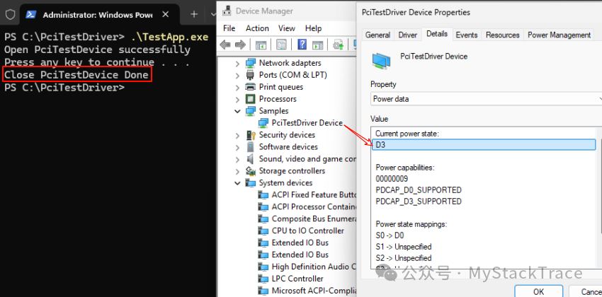
After modifying the driver, we can test it to see if the PCIe device can enter D0 operational state after the test program opens the device file. We will still use the previous test program; after opening the device file and obtaining the handle, the program executes the “pause” command to halt, and then we check the Power data of the device in the device manager, which should now be in D0 state.
After a while, press any key to let the test program continue executing, which means closing the device file handle. We then check the Power data of the device in the device manager again, and it should change to D3 state.
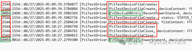
Finally, let’s check the logs output by the driver during this process. We can see that when the application opens the device file, the process enters kernel mode and eventually calls the FileCreate function. We will also find that the D0Entry function is called, and from the leftmost column of the log, we can see that the process ID calling D0Entry is clearly different from the process ID calling FileCreate; 0004 is the process ID of the Windows system thread, indicating that this D0Entry is called by the system itself (WDF driver framework) after receiving the notification from the FileCreate call to WdfDeviceStopIdle. From the timestamp difference between the logs output by the FileCreate and FileClose functions, we can see that the application closed the file after approximately 50 seconds of opening the device file, and D0Exit is called only after the device file is closed, indicating that this PCIe device indeed enters D3 state only after the test program closes the file handle, confirming that our modifications to the driver are as expected.