Raspberry Pi Physics: Measuring the Speed of Light
Title: Raspberry Pi Physics: Measuring the Speed of LightThis is a paper published by Tom Ekkens in the 2024 issue of The Physics Teacher.
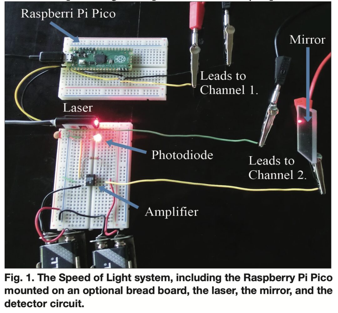
This article measures the speed of light using relatively inexpensive equipment, as using a Fizeau-Foucault apparatus and a beam splitter can be quite costly. The instruments in this paper mainly consist of a modulated laser, a modulation source, and a detector.
Considering that light takes 3.3 nanoseconds to travel 1 meter, the measurement error for a 20m length using an oscilloscope with a time resolution of 2 nanoseconds at a gigasampling frequency is within 3%. When the modulation frequency of the hardware is below 1 MHz, nanosecond-level changes are insufficient to be effective. However, if the signal frequency is significantly higher than 10 MHz, general oscilloscopes cannot sample enough data points to accurately describe the waveform. Therefore, the laser, modulation source, and detector should be capable of operating within the range of 1 to 10 MHz.

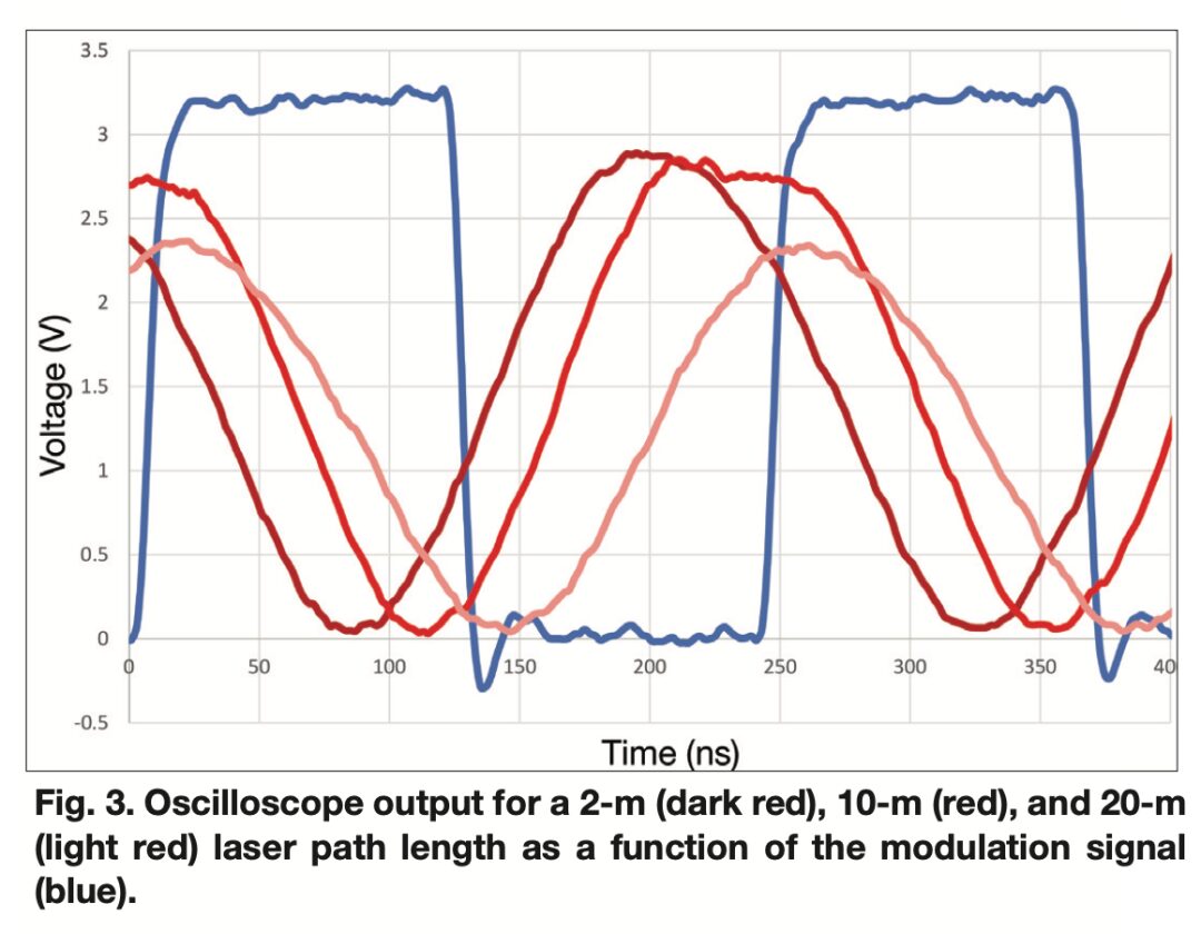
To collect data, the laser, detector, and oscilloscope are placed at one end of the hallway or sidewalk, relatively close to each other. A mirror is placed in the hallway to reflect the laser beam into the detector. A typical output from the oscilloscope is shown in Figure 3, where the blue line represents the modulation signal generated by the Raspberry Pi Pico. The oscilloscope triggers on the rising edge of this signal. The detector output is represented by one of the three red lines, corresponding to different path lengths.

If the laser and detector are perfect, the output from the detector would be a square wave similar to the modulation signal, but with a slight time delay. However, capacitance on both sides will round the sharp edges of the square wave, making the output signal appear more like a sine wave.
If the light intensity is too high, the sine wave will flatten around the maximum voltage, as shown by the red line in Figure 3. To minimize the uncertainty caused by these flattening effects, it is best to measure the time at the minimum of the sine wave.
For the dark red line in Figure 3, the laser path length is 2 m, and the time at which the dark red line reaches its minimum is 88 ns from the trigger point. The path length for the red line is 10 m, reaching its minimum at 116 ns. The light red line has a path length of 20 meters, reaching its minimum at 148 nanoseconds.
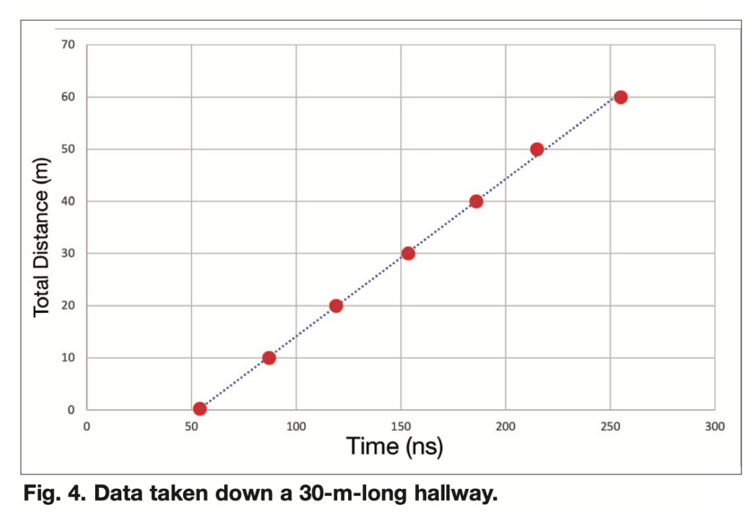
Figure 4 plots the path length against the delay time.

The measured speed of light is approximately, with an error within 1%.
Original link: https://doi.org/10.1119/5.0124070
