
Introduction
In our previous article “What is an Embedded System (Part 2) — Deposition Model”, we mentioned:
Current computer technology is approximately 20 years ahead of embedded technology; today’s embedded systems are comparable in resources, theory, and methodology to the cutting-edge computer technology of the 1980s.
GorgonMeducer, WeChat Official Account: Bare Metal Thinking – What is Embedded (Part 2) — “Gravity” and “Deposition”
This means that some technologies applied to personal computers in the early 21st century might gradually be introduced into Deep Embedded Systems — the typical systems that everyone is familiar with are microcontrollers or Cortex-M processors.
Arm is an “old” player in the industry ecosystem — almost all actions are considered from an ecological perspective — so to understand why Arm is customizing a graphics driver for “Cortex-M” at this time, we must understand what has happened in the entire deep embedded ecosystem. To do this, let’s imagine:
-
You think smart watch applications should be popular, or IoT terminal devices with color screens should be in demand. -
Considering low power consumption and low cost, it seems reasonable for some products to use Cortex-M (instead of Cortex-A) to achieve this. Thus, your company defines a Cortex-M processor equipped with a 2D graphics acceleration engine. -
The chip is quickly produced, and the development board is equipped with a 480*272 resolution touchscreen, combined with a specially designed PCB (and a highly recognizable PCB color) — it looks high-end! Impressive! Classy! -
But then a problem arises:
-
There is completely no third-party 2D benchmarking software for microcontrollers (bare metal or RTOS) (the professional term is Benchmark) — how can this demonstrate the power of your hardware? How can evaluation agencies present complex 2D processing in a simple numerical form to the public? -
There are so many third-party GUI providers, all of whom have GUI products for Cortex-M chips, but how can I convince them to add support for my chip?
-
Your previous products were somewhat popular in Cortex-A and Linux environments.
-
Recently, many software companies have targeted the deep embedded market, providing customized GUI products, such as Microsoft’s GUIX, Qt’s Qt for Cortex-M. So you quickly provided corresponding GUI products, but then the problems arose:
-
There is completely no third-party 2D benchmarking software for microcontrollers……
-
Unlike the relatively standardized software environment of Cortex-A and Linux, the deep embedded environment is too fragmented:
-
Different LCD specifications
-
Different hardware interfaces connecting to LCD (different LCD bandwidth)
-
Different operating modes of LCD (with or without LCD peripheral drivers, types of drivers)
-
Different resources of target chips, different system frequencies
-
Different software environments — countless RTOS, and even bare metal
-
Every 2D graphics acceleration hardware provided by chip manufacturers is different…
-
In summary, if you want to support a hardware platform, you need to port and customize it for its hardware…
-
Considering limited team resources, the officially supported hardware is also limited…
In summary:
-
The chip manufacturer provides a “customized” 2D graphics acceleration hardware to give the chip a “differentiated” selling point — but from another perspective, it actually exacerbates the fragmentation of hardware. At the same time, chip manufacturers are also struggling to find a large number of GUI protocol stacks to provide software support for their chips;
-
GUI software providers are struggling with the enormous porting workload caused by hardware fragmentation. They wish their teams could focus more on developing the GUI itself rather than being exhausted by providing “official support” for new hardware platforms.
Suddenly, one day, both parties, exhausted and panting, realize something is off, and they silently turn their heads towards Arm —this so-called neutral third party in the ecosystem…

-
Chip Manufacturer: Just write the driver for your 2D acceleration engine according to my standards — you will instantly gain support from all GUIs based on Arm-2D;
-
GUI Provider: Wherever you need hardware acceleration in your GUI, you can directly call the API I provide — if the chip actually has hardware acceleration, it will naturally get accelerated; if the chip does not have hardware acceleration, then use my provided software optimization algorithm — in summary, it’s one port, and it works everywhere, regardless of whether there is actual hardware acceleration.
-
For bare metal users: Don’t worry, I know your hardware platform resources are tight — you can’t afford a professional GUI protocol stack: you generally either don’t use GUI or just write a simple GUI yourself — don’t worry: Arm-2D also brings you a big gift, allowing you to easily achieve “those unimagined paths”.

“What what?” Bare metal users exclaimed : “Isn’t this a B2B matter? Why suddenly do we have our benefits?”
Stay tuned; I will explain later in the article.
2D Processing Benchmark for Deep Embedded Systems
-
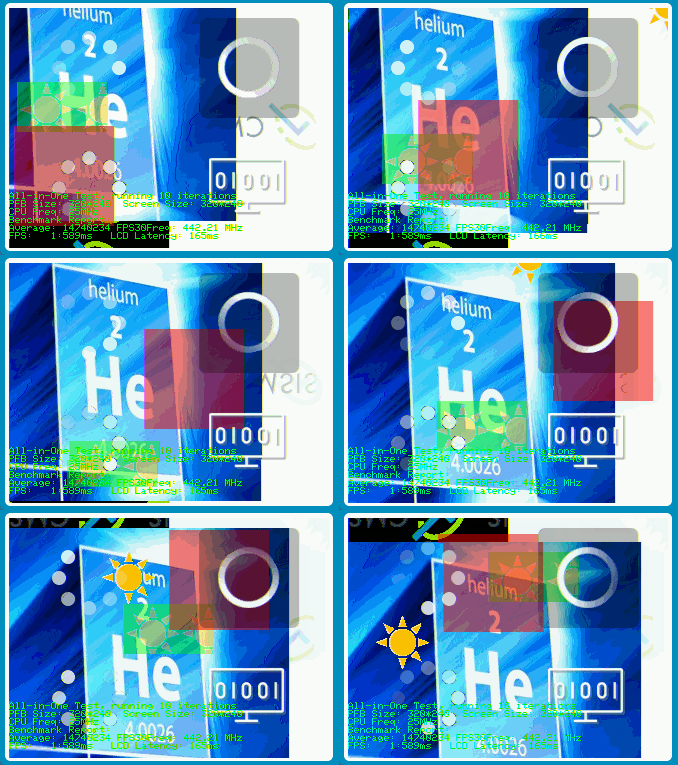
Establish a typical 2D graphics processing load to simulate the workload and complexity required in daily GUI application scenarios (the static screenshot of this benchmark is approximately the one below; note that this is the effect on the simulator, so the frame rate is very low):
-
Make different layers float at different speeds and angles to cover more possible scenarios — simulating different complexities that may occur in daily GUIs;
-
Render 1000 frames, recording the number of CPU clock cycles consumed for each frame, and providing minimum, maximum, and average information.
-
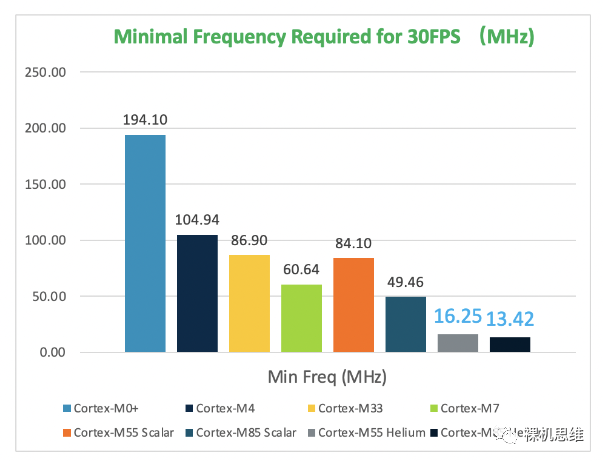
Using the average cycle count required for frame rendering as a basis, calculate the “minimum processor frequency required for 30FPS” — and use this value as the benchmark result.
It is worth noting that:
-
This benchmark software does not calculate the time consumed for “sending data from RAM to LCD” when counting the cycles required to render a frame — because the time consumed for “refreshing video memory” is determined by the connection method (or transmission bandwidth) between the chip and the LCD, and is unrelated to the chip’s 2D graphics processing capability.
-
In fact, it is common for friends to sarcastically say when seeing the dynamic effects of the benchmark: “Hmm, very cool, I just want to know how much capability the processor has left to handle specific applications.” In fact, the “minimum clock frequency required for 30FPS” is intended to intuitively answer this question.
-
Cortex-M0+ needs about 194MHz, in other words: if your Cortex-M0+ runs at 250MHz, you still have 56MHz of CPU performance available for applications.
The Raspberry Pi Pico running dual-core Cortex-M0+ at 250MHz is ecstatic
-
Cortex-M3/M4 requires about 105MHz, meaning if your chip runs at 216MHz, you still have about 111MHz available for specific applications (by the way, which Cortex-M4 doesn’t run at over 100MHz these days?)
-
Meanwhile, Cortex-M55, which uses SIMD instruction set acceleration (Helium instruction set), only needs 16MHz to achieve a refresh rate of 30FPS —— which is truly terrifying.
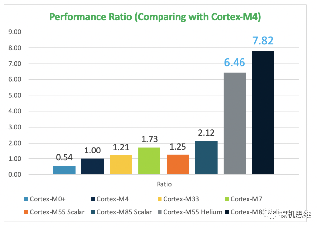
More intuitively, here is the official 2D performance multiplier comparison (with Cortex-M4 performance as the baseline). Cortex-M55 Helium is nearly 6 times the performance of Cortex-M4 and 10 times that of Cortex-M0! — If Arm-2D is a graphics driver, then Cortex-M55 Helium is a Cortex-M processor with an integrated “graphics card“.

Preparation
void Disp0_DrawBitmap (uint32_t x, uint32_t y, uint32_t width, uint32_t height, const uint8_t *bitmap)Here, the relationship between the five parameters is shown in the following diagram:
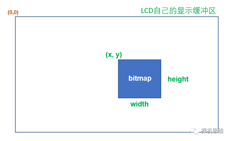
Many LCDs support a concept called “operating window“; this window is actually the rectangular area shown in the above diagram — once you set the window through instructions, the subsequent continuous pixel writes will be automatically filled into the specified rectangular area (without the user having to consider when to wrap lines).
If you are fortunate enough to use a chip with an LCD controller — the display buffer of the LCD is directly mapped to the 4GB address space of the Cortex-M chip, we can use simple memory read and write operations to implement the above function. For example, with the STM32F746G-Discovery development board:
//! STM32F746G-Discovery#define GLCD_WIDTH 480#define GLCD_HEIGHT 272#define LCD_DB_ADDR 0xC0000000#define LCD_DB_PTR ((volatile uint16_t *)LCD_DB_ADDR)void Disp0_DrawBitmap (uint32_t x, uint32_t y, uint32_t width, uint32_t height, const uint8_t *bitmap) { volatile uint16_t *phwDes = LCD_DB_PTR + y * GLCD_WIDTH + x; const uint16_t *phwSrc = (const uint16_t *)bitmap; for (int_fast16_t i = 0; i < height; i++) { memcpy ((uint16_t *)phwDes, phwSrc, width * 2); phwSrc += width; phwDes += GLCD_WIDTH; }}
How to Obtain the Installation Package
https://github.com/ARM-software/Arm-2D/releases
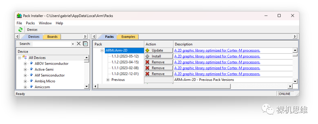
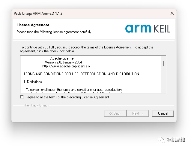
Arm-2D deployment is incredibly simple, and most of the work can be completed by checking the corresponding options in RTE. Please refer to the step-by-step tutorial below:
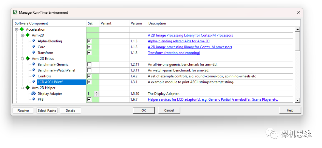
In the MDK project, select Project -> Manage -> Run-Time Environment to open the RTE configuration window:
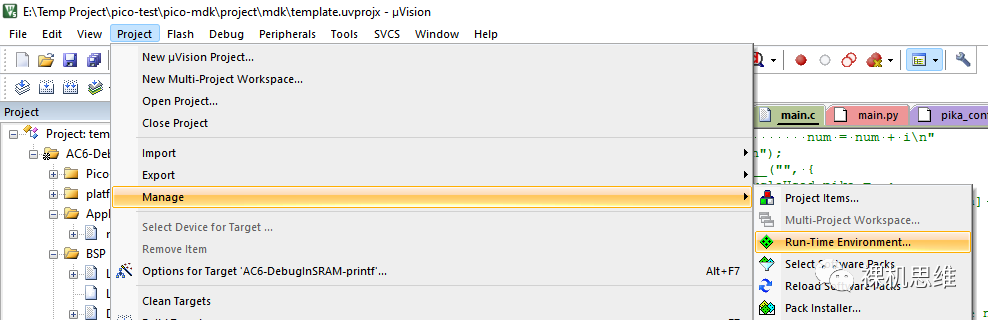

-
Core: The core of Arm-2D (required) -
Alpha-Blending: Most operations related to transparency, such as mask-based copying, transparent layer composition, transparent color block filling, etc. -
Transform: Operations like rotation, scaling, etc. (supports masks, cutouts, and transparency)
-
FPB: Partial Frame-Buffer module, the core component supporting partial refreshes -
Display Adapter: A code template that uses PFB to adapt to the underlying LCD driver, helping us quickly establish a bridge between upper-level drawing and lower-level LCD refreshing. Generally, the Display Adapter corresponds one-to-one with the screen: if you have one screen, select “1”; if you have two screens, select “2”, and so on.
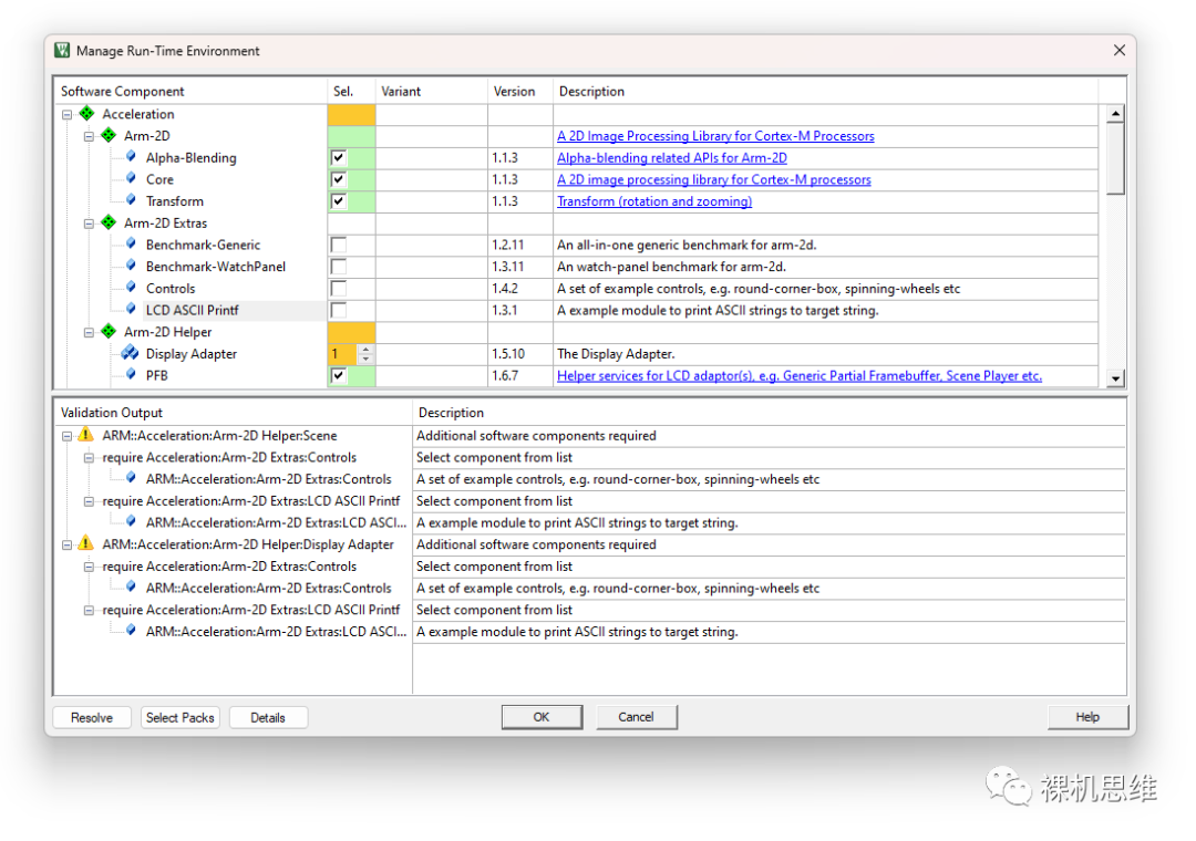
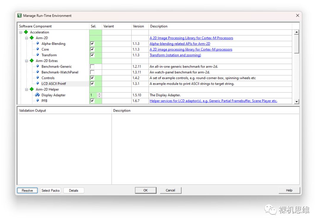

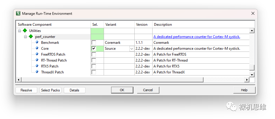
For the convenience of subsequent development, it is strongly recommended to download and install the perf_counter module. For specific steps, please refer to the article “【Super Embedded System Performance/Time Toolbox】”; here are the key steps:
-
Follow the WeChat official account 【Bare Metal Thinking】 and send the keyword “perf_counter” to obtain the corresponding cmsis-pack -
Download and install the cmsis-pack -
Open RTE, find Utilities, and check Core in perf_counter, recommended to deploy in Source form -
If an orange warning appears, click the Resolve button to resolve it
We will see a window similar to this:
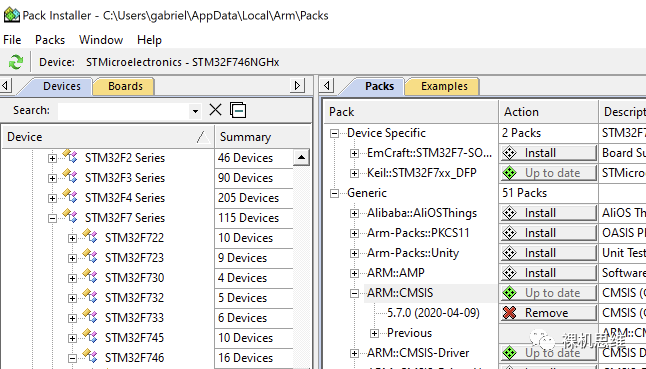
In the right half of the Packs tab, find ARM::CMSIS, and ensure it shows “Up to date”. If not, click the corresponding button to update. The CMSIS version required for Arm-2D must be at least 5.7.0 (if you are using Cortex-M55, the version must be at least 5.8.0).
2. Using the button in the middle of the toolbar, open the RTE configuration window:
In the Software Component list, expand CMSIS, and check CORE and DSP. It is important to note that if there is a Source option in the DSP section, please select the Source option — this will allow us to directly compile the CMSIS-DSP library in source code form.
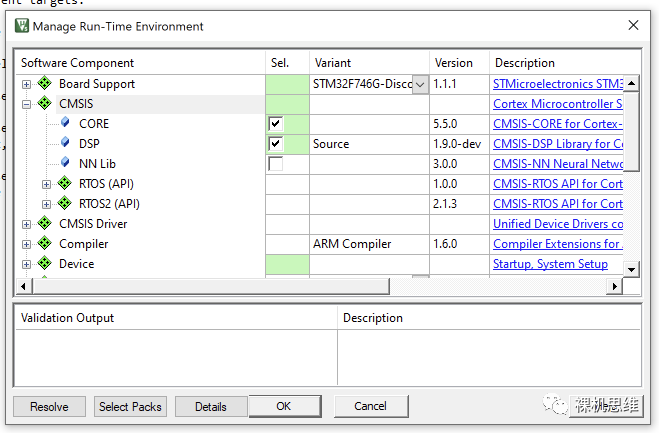
In addition, if you are unsure whether the CMSIS used in RTE is the latest version, you can click the Select Packs button:
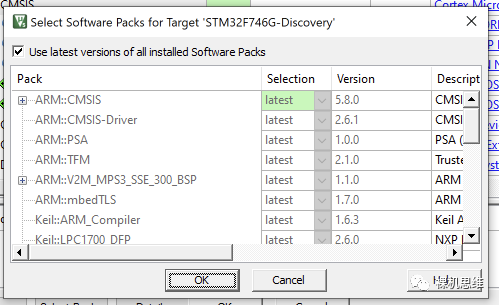
If the top of the window shows “Use latest Software Packs for Target” is checked, you can basically rest assured. Click OK to close the dialog, and we have successfully added CMSIS to the compilation. Since we chose to compile CMSIS in source code form, we may also need to perform additional settings on the source code of CMSIS-DSP.
At this point, we should be able to successfully complete the compilation.

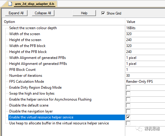
Fill in the correct information according to your screen:
-
Color Depth (Screen Colour Depth)
-
Horizontal Resolution (Width of the screen)
-
Vertical Resolution (Height of the Screen)
-
Width of Partial Refresh Buffer Block (Width of the PFB Block), generally consider the width of a full line or half a line of pixels
-
Height of Partial Refresh Buffer Block (Height of the PFB Block), generally recommended to be 1/10 of the screen pixel height. When RAM is scarce, consider 8 or 1.
-
When calculating frame rates, how many frames to update data (the Number of iterations), the default is 30, selecting 0 will turn off the real-time frame rate calculation function.
-
Real-time frame rate statistics mode (FPS Calculation Mode), the default is Render-Only FPS (only calculates the frame rate of the Arm-2D rendering part), while Real FPS calculates the actual frame rate.
Save and close the window.
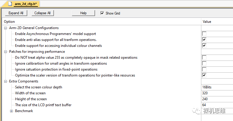
-
Enable Asynchronous Programmers’ model support: Currently recommended to be disabled -
Enable anti-alias support for all transform operations: Enables anti-aliasing for rotation and scaling operations -
Enable Support for accessing individual Colour channels: Recommended to be enabled when your target screen is RGB888 and you need to support PNG images.
-
Do not check -
After completing the application, try checking them one by one: If they do not have a significant impact on the application, check them for a performance boost.
In the source code file where the main() function is located, include the header file:
#include "arm_2d.h"int main(void) { system_init(); // System initialization including LCD ... arm_irq_safe { arm_2d_init(); // Initialize arm-2d } ... while(1) { ... }}#include "arm_2d_disp_adapters.h"int main(void) { system_init(); // System initialization including LCD ... arm_irq_safe { arm_2d_init(); // Initialize arm-2d } // Initialize Display Adapter 0 disp_adapter0_init(); while (true) { ... // Execute Display Adapter refresh task disp_adapter0_task(); ... } }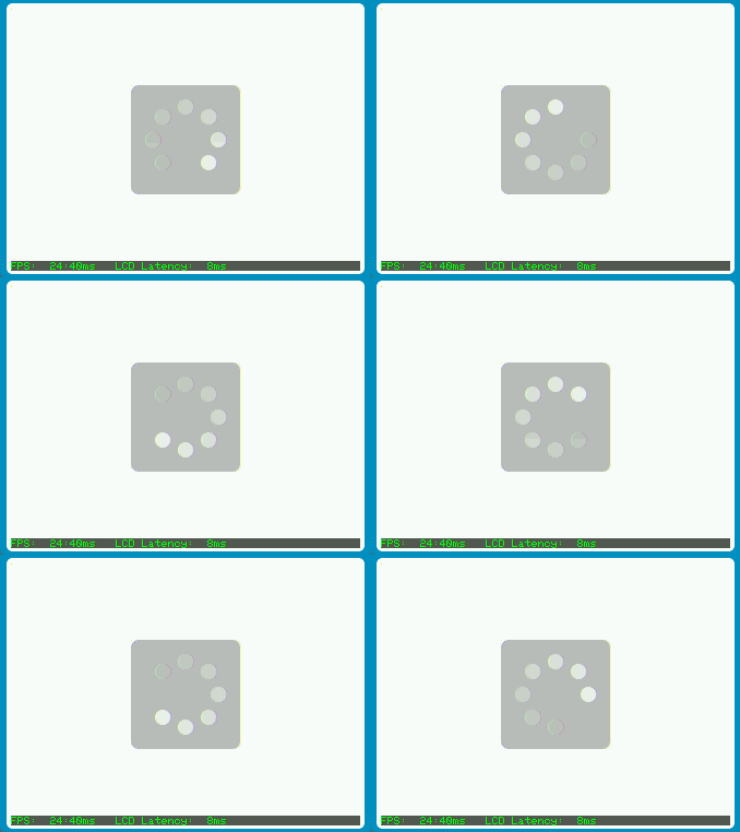

-
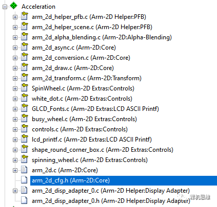
In Acceleration, you can find arm_2d_disp_adapter_0.c, open it to find the key code for using arm-2d -
The Display Adapter carries a default scene (Scene), and its drawing function is as follows:
staticIMPL_PFB_ON_DRAW(__pfb_draw_handler){ ARM_2D_UNUSED(pTarget); ARM_2D_UNUSED(ptTile); ARM_2D_UNUSED(bIsNewFrame); arm_2d_canvas(ptTile, __top_container) { arm_2d_fill_colour(ptTile, NULL, GLCD_COLOR_WHITE); arm_2d_align_centre(__top_container, 100, 100) { draw_round_corner_box( ptTile, &__centre_region, GLCD_COLOR_BLACK, 64, bIsNewFrame); } busy_wheel2_show(ptTile, bIsNewFrame); } arm_2d_op_wait_async(NULL); return arm_fsm_rt_cpl;}-
It is easy to observe that the above two functions actually call Disp0_DrawBitmap() and arm_2d_helper_pfb_report_rendering_complete() before and after:
Common Issues
Issue 1: Installation of CMSIS-Pack failed
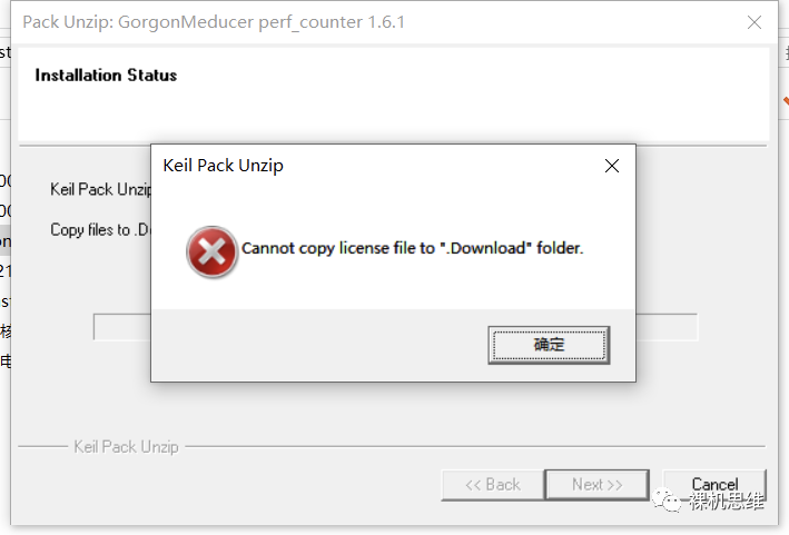
It is worth emphasizing that MDK provides a Community version for the open-source community, which, except for commercial use, has almost no restrictions (no restrictions on chips, code size, debugging). The Community version is essentially a type of License, and the installation files are the same as other versions. Friends interested in this “official free version” can obtain it through the following link:
https://www.keil.arm.com/mdk-community/
If you are particularly unlucky and installing the latest MDK does not resolve the above issue, you can try to “fight” by using the import function of Pack-Installer — open Pack Installer , then click File->Import:
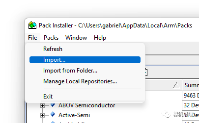
If it still doesn’t work, please confirm whether your MDK is installed in the default installation directory (C:\Keil_v5); if not, try reinstalling it to the default directory.
If all else fails… just try another computer.

This is due to the CMSIS version included in the project being too low and conflicting with the CMSIS deployed in RTE. For specific solutions, please refer to the article “Guide to the ‘Hellish Achievements’ of CMSIS Players”.
Such issues arise when there is an independent CMSIS in your MDK project, and this CMSIS conflicts with the CMSIS added in RTE (the CMSIS version in the project is too outdated). For specific solutions, please refer to the article “Guide to the ‘Hellish Achievements’ of CMSIS Players”; I will not elaborate here.
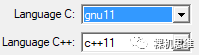
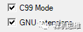
In addition, check whether you have correctly enabled GNU extensions and the corresponding C standards (Arm Compiler 5 requires C99, Arm Compiler 6 requires gnu99)
Issue 4: Prompt cannot find __aeabi_assert
#include "arm_2d.h"#include "cmsis_compiler.h"#if defined(__MICROLIB)void __aeabi_assert(const char *chCond, const char *chLine, int wErrCode) { ARM_2D_UNUSED(chCond); ARM_2D_UNUSED(chLine); ARM_2D_UNUSED(wErrCode); while(1) { __NOP(); }}#endifIssue 4: Prompt cannot find Disp0_DrawBitmap
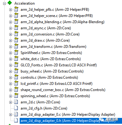
At this point, we can see the added code files in Acceleration:
Note that each file here has a corresponding number, indicating the corresponding Display Adapter template. Each Display Adapter needs its own low-level refresh function: Dispn_DrawBitmap(), please refer to the 【Preparation】 section of this article for details.
Issue 5: Hardfault occurs
Check the stack size; it is recommended to be above 0xC00 (3K) for ease.
Conclusion
-
Each scene consists of (optional) background and foreground -
Users can -
Predefine a series of scenes and switch them sequentially -
Also, append (Append) new scenes at runtime via API -
The scene switching will automatically avoid frame tearing issues
Although arm_2d_disp_adapter_0.c has already demonstrated the use of the Scene Player for us, to lower the learning threshold for everyone, I will detail this “scene-based” low-cost GUI design method in the next article.
If you like my thinking, and find my article enlightening,
Please make sure to “like, bookmark, and share”; it’s very important to me! Thank you!
Welcome to subscribe to Bare Metal Thinking