
PCB, Printed Circuit Board. As the name suggests, it is a board with circuits printed on it. It is known as a printed circuit board, or hard board.
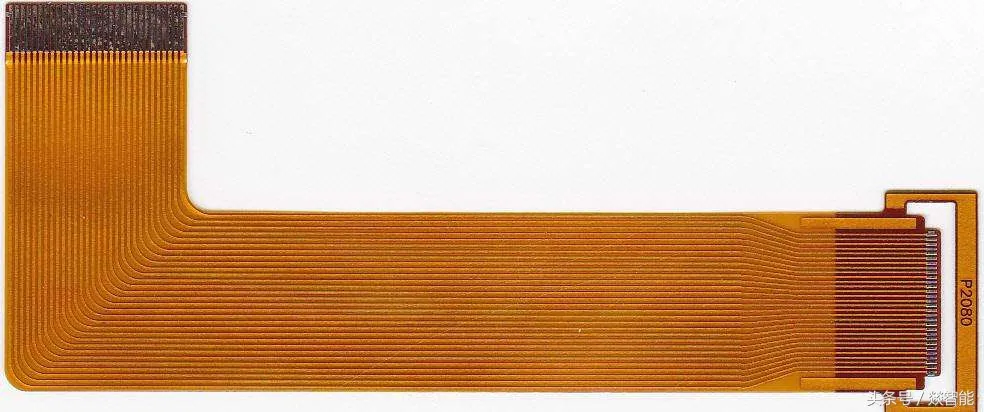
FPC board
FPC, Flexible Printed Circuit. As the name implies, this is a circuit that is also printed and is flexible. It is known as a flexible circuit board, or soft board. Typically, it is yellow.
There is also a type of circuit board that is partially hard and partially soft, commonly referred to as a rigid-flex board, or rigid-flex PCB (rigid and flexible).
Working Principle of Circuit Boards: A board with circuits is used to mount and connect various components. After soldering the components onto the circuit board, the pins of the components are connected through the circuits on the board, transmitting electrical signals to each other. It is similar to how the light in your home is connected to the switch with wires; the light bulb, switch, and circuit are miniaturized and placed on a single board, which is the circuit board.
FPC and PCB
PCB, circuit board, motherboard, board, these common terms usually refer to circuit boards, and subsequent articles will not specifically differentiate these concepts.
The biggest difference between FPC and PCB is that one is soft and the other is hard. The soft board can be rolled and bent. However, note that the soft board cannot be bent arbitrarily; it has thickness, and if it is bent too many times or the bending radius is too small, it can break. In the past, flip phones often experienced screen flickering after prolonged use because the FPC connecting the screen and motherboard had bent too many times and broke.
PCB and FPC are manually designed by hardware engineers. Starting from the schematic output netlist, structural engineers provide the board framework drawings, which are then imported into the PCB file. A large number of components are arranged one by one, and the actual circuits are drawn according to the netlist, completing the design of a PCB.
The PCB drawings correspond completely to the physical PCB; whatever is drawn on the drawing is exactly what the PCB looks like when received.
Some multilayer circuit board products, such as 8-12 layer computers and mobile phones, are often too complex to draw, so there are dedicated PCB engineer positions responsible for drawing. They are also called Layout engineers.
Here we raise a few questions:
If there are too many circuits to fit on one side, what do we do? Then we use two sides. If two sides are still not enough, we can add two more, making it a 4-layer board. This is the concept of multilayer circuit boards. Note that layers are called Layer, not floor; don’t make that mistake. If 4 layers are not enough, we can continue to add more, even dozens of layers. For example, computer motherboards, due to their large size, are generally 4 or 6 layers. Mobile phone motherboards, being compact, are generally 8 to 12 layers. Many military-grade motherboards, which require high signal isolation, often exceed twenty layers.
Those who lack spatial thinking may find it hard to imagine why multilayer boards are necessary. On a single-layer circuit, two different circuits cannot cross; if they do, it results in a short circuit. If they cannot cross directly, can they go around? Yes, two wires can cross by going around, but if a third wire comes in, it cannot go around anymore. Therefore, it is necessary to increase a layer to allow for spatial crossing. Thus, for multilayer boards, the direction of the wiring on each layer is generally uniform; one layer is horizontal, and another is vertical, ensuring that there is always a way to cross in space.
How are so many layers of circuits connected? This is achieved through vias. Vias are holes that allow electrical signals to pass through. They are similar to stairs in a building; to move from one floor to another, you need to use stairs. To connect one layer of circuit to another, vias are required.
Why are there 4, 6, or 8 layer circuit boards? Why not 3, 5, or 7 layers? Actually, it is possible to make them; the manufacturing process for multilayer boards is to first create the inner 2 layers, then attach 2 outer layers, and finally attach 2 more layers. If the inner 2 layers are completed first and then only one outer layer is attached, it is technically feasible, but the process is not much different from attaching 2 layers, and at the same price, it is certainly preferable to add 2 layers rather than just 1.
“Manually drawn”? Nowadays, with cars being self-driving and AlphaGo defeating humans, how can something as “simple” as drawing circuit boards still require manual work? This is indeed a big question. In the decades since the invention of PCBs, software companies have been eager to automate routing. However, there are too many types of components, each with different requirements for the circuits, and each signal has its own requirements as well. Users spend a lot of time just modeling. The routing methods for each wire are stored in the minds of hardware engineers, making it difficult to input all the rules. In unpredictable situations, computer programs cannot match the human brain. Therefore, for simple circuit boards, manual drawing is faster, while for complex circuit boards, it is challenging for programs to produce the desired results, leading to a very low adoption rate of automated routing, with almost no one using it.
PCB and FPC are often used as examples to test engineers’ learning abilities. In both software and hardware industries, there are numerous English and Chinese abbreviations, but many people only remember the abbreviations without knowing the full names. Some engineers influenced by turnkey and unconventional methods may work for years without knowing the full names of PCB and FPC. Some may ask, “Isn’t it enough to know what they are? Why do I need to know the full names?” Because the full names represent the true meaning of the terms, encompassing their principles. Only knowing the abbreviation without the full name is a typical case of “knowing the phenomenon but not the principle.”
When entering a new industry, there will be a plethora of new terms. First, you need to know what the term is called, then understand how it works, and finally grasp why it is done this way. This is the principle of the “three whys” mentioned earlier. Knowing the name allows you to enter the field; understanding the working principle enables problem analysis; knowing the reason allows for broader application. The more terms you know, the broader your knowledge base; the more thoroughly you study each knowledge point, the deeper your technical expertise.
In the explanation of a term, you can generally discover other unfamiliar terms, and through the explanations of these terms, you can find even more new terms. Ultimately, through the network of term explanations, you can deduce and understand the entire knowledge system.
Many newcomers often feel overwhelmed by the vast ocean of knowledge points, not knowing where to start or how to ask questions. In fact, as long as you follow the “three whys” principle mentioned above and explore from point to area, gradually learning to ask yourself questions, you can quickly get started. The key to learning ability lies in how to ask yourself questions; the more you ask why, the faster you will learn.


Some screenshots from electronic books
 【Complete Collection of Hardware Learning Materials】