1 FlexRay Bus Introduction
1.1 FlexRay Generation and Development
As the number of functions enhancing safety and comfort in cars continues to increase, the number of sensors, transmission devices, and Electronic Control Units (ECUs) required to implement these functions is also on the rise. Today, high-end cars have more than 100 ECUs, and without adopting new architectures, this number may continue to grow. The coordination between ECU operations and numerous automotive buses is becoming increasingly complex, severely hindering the development of X-by-Wire technology (replacing heavy mechanical/hydraulic components with lightweight, efficient, simpler, and fault-tolerant electrical/electronic systems). Even if complexity issues can be solved, traditional automotive buses lack the determinism and fault tolerance necessary for X-by-Wire. For instance, the transmission of safety-related information requires absolute real-time capabilities; such high-priority information must be transmitted correctly within a specified timeframe, such as braking, where the information from the brake pedal to the braking action must be transmitted immediately and accurately without any uncertainties. Additionally, the increasing data transmission volume across automotive networks demands communication buses with high bandwidth and data transmission rates. Currently prevalent automotive bus technologies like CAN and LIN do not meet the future automotive application requirements due to their lack of synchronization, determinism, and fault tolerance.
BMW and DaimlerChrysler recognized early on that traditional solutions could not meet the future needs of the automotive industry, especially the requirements for automotive X-by-Wire systems. In September 2000, BMW and DaimlerChrysler, in collaboration with Philips and Motorola, established the FlexRay Consortium. This consortium is dedicated to promoting the global adoption of the FlexRay communication system, establishing it as the standard protocol for advanced powertrains, chassis, and X-by-Wire systems. Its specific tasks include defining FlexRay requirements, developing the FlexRay protocol, defining the data link layer, providing supporting controllers for FlexRay, developing FlexRay physical layer specifications, and implementing foundational solutions.
FlexRay offers a multitude of features not found in traditional in-vehicle communication protocols, including:
(1) High Transmission Rate: Each channel of FlexRay has a bandwidth of 10 Mbps. It can operate as a single-channel system like CAN and LIN networks, or as a dual-channel system, achieving a maximum transmission rate of 20 Mbps, which is 20 times the highest operating rate of CAN.
(2) Synchronized Time Base: The access method used in FlexRay is based on a synchronized time base. This time base is automatically established and synchronized through the protocol and provided to applications. The accuracy of the time base ranges between 0.5μs and 10μs (typically 1-2μs).
(3) Determinism: Communication occurs in a continuously repeating cycle, with specific messages having fixed positions within the communication cycle, allowing receivers to know in advance when messages will arrive. The temporary deviation in arrival times is very small and is guaranteed.
(4) High Fault Tolerance: Robust error detection and fault tolerance are critical aspects considered in FlexRay design. The FlexRay bus uses Cyclic Redundancy Check (CRC) to verify errors in communication. Through dual-channel communication, FlexRay can provide redundancy, and using a star topology can completely resolve fault tolerance issues.
(5) Flexibility: During the development of the FlexRay protocol, a primary focus was on flexibility, reflected in several aspects: ① Support for various network topologies; ② Configurable message lengths: payload lengths can be set according to actual control application needs; ③ When using dual-channel topology, it can be used to either increase bandwidth or transmit redundant messages; ④ The timing for static and dynamic message transmission within the cycle can be determined based on specific applications.
2 FlexRay Communication Protocol and Mechanism Principles
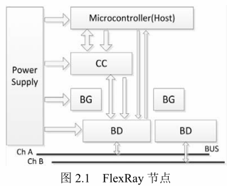
The ECU (Electronic Control Unit), or node, is a control unit that independently performs corresponding functions within the onboard network. It mainly consists of a Power Supply system, Host processor, embedded FlexRay communication controller, optional Bus Guardian, and Bus Driver, as shown in the figure. The Host processor provides and generates data, which is transmitted through the FlexRay communication controller. The number of Bus Drivers (BD) and Bus Guardians (BG) corresponds to the number of channels and connects to the communication controller and microprocessor. The bus monitoring logic must be independent of other communication controllers. The bus driver connects the communication controller to the bus or connects the bus guardian to the bus.
The two communication processes of the node are:
(1) Sending Data: The Host sends valid data to the CC, which encodes it to form a data bit stream and sends it to the corresponding channel via the BD.
(2) Receiving Data: At a certain moment, the BD accesses the stack and sends the data bit stream to the CC for decoding, with the data portion transmitted to the Host by the CC.
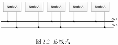
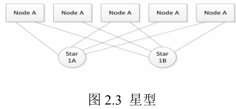
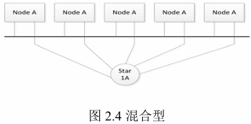
FlexRay’s topology is mainly divided into three types: bus, star, and bus-star hybrid.
Typically, FlexRay nodes can support two channels, thus can be divided into single-channel and dual-channel systems. In a dual-channel system, not all nodes need to connect to both channels.
Compared to bus structures, star structures provide advantages in that they offer point-to-point connections between receivers and transmitters. This advantage is particularly evident in high transmission rates and longer transmission lines. Another significant advantage is error isolation. For instance, if two lines used for signal transmission short-circuit, the bus system cannot continue communication on that channel. In a star structure, only the node connected to the short-circuited line is affected, while all other nodes can continue to communicate with each other.
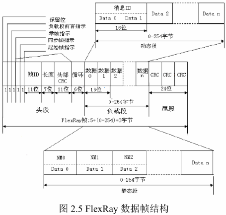
A data frame consists of a header segment, a payload segment, and a trailer segment. The FlexRay data frame format is shown in Figure 2.5.
(1) The header segment consists of 5 bytes (40 bits) including the following bits:
1. Reserved bit (1 bit): Reserved for future expansion;
2. Payload segment prefix indication (1 bit): Indicates the vector information of the payload segment;
3. Invalid frame indication (1 bit): Indicates whether the frame is invalid;
4. Synchronization frame indication (1 bit): Indicates whether this is a synchronization frame;
5. Start frame indication (1 bit): Indicates whether this frame is a start frame;
6. Frame ID (11 bits): Used to identify the frame and its priority within time-triggered frames;
7. Payload segment length (7 bits): Indicates the number of words that can be transmitted in a frame;
8. Header CRC (11 bits): Used to detect errors during transmission;
9. Cycle count (6 bits): Increments by 1 for all nodes at the start of each communication.
(2) The payload segment is the part used for data transmission, and the FlexRay payload segment contains 0 to 254 bytes of data.
For dynamic frames, the first two bytes of the payload segment are typically used as the information ID, allowing receiving nodes to determine whether it is the required data frame based on the received ID.
For static frames, the first 13 bytes of the payload segment are the network management vector (NM), used for network management.
(3) The trailer segment contains only a 24-bit checksum field, which includes the CRC checksum calculated from the header and payload segments. When calculating the CRC, the data from the reserved bit to the last bit of the payload segment is input into the CRC generator for calculation based on the order of network transmission.
2.4 Encoding and Decoding
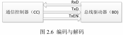
The encoding process is essentially the process of preparing and “packing” the data to be sent, such as adding various check bits, IDs, etc. Encoding and decoding mainly occur between the communication controller and the bus driver, as shown in Figure 2.6.
Where RxD is the receiving signal, TxD is the transmitting signal, and TxEN is the communication controller’s data request signal. The binary representation of the information uses the “non-return-to-zero” code. For dual-channel nodes, the encoding and decoding processes on each channel are performed simultaneously.
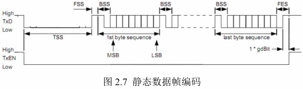
TSS (Transmission Start Sequence): Used for initializing the node and network communication docking, is a short low-level signal.
FSS (Frame Start Sequence): Used to compensate for quantization errors that may occur in the first byte after TSS, is a high-level signal of one bit. BSS (Byte Start Sequence): Provides data timing information to the receiving node, consisting of one high-level and one low-level signal.
FES (Frame End Sequence): Used to indicate the end of the last byte sequence of the data frame, consisting of one low-level and one high-level signal.
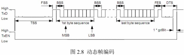
DST (Dynamic Segment Tail Sequence): Used only for dynamic frame transmission, to indicate the precise timing of the transmission time slot action point within the dynamic segment, and to prevent the receiving segment from prematurely detecting the network idle state. It consists of a variable-length low-level signal and one high-level signal.
Assembling these sequences with valid bits (from the most significant bit MSB to the least significant bit LSB) constitutes the encoding process, ultimately forming the data bit stream that can propagate on the network.
In media access control, an important concept is the communication cycle, as shown in the figure. A communication cycle consists of four parts: Static Segment, Dynamic Segment, Symbol Window, and Network Idle Time. FlexRay provides two choices for media access timing: the static segment uses Time Division Multiple Access (TDMA), consisting of fixed time slots that cannot be modified, and all time slots are of equal size, used for transmitting periodic data information; the dynamic segment uses Flexible Time Division Multiple Access (FTDMA), consisting of smaller time slots that can be expanded or contracted as needed, typically used for transmitting event-controlled messages. The symbol window is used to transmit characteristic symbols. The network idle time is used for clock synchronization processing.
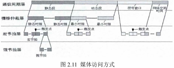 The arbitration layer contains an arbitration network, which forms the backbone of FlexRay media arbitration. In the static segment, the arbitration network consists of continuous time intervals called static slots; in the dynamic segment, it consists of continuous time intervals called minislots.
The arbitration network layer is built on top of a macro tick layer composed of macro ticks. The time of each local macro tick is an integer multiple of the time of a micro tick. The assigned macro tick edges are called action points. Action points are specific moments when transmission starts and ends.
The micro tick layer is composed of micro ticks. Micro ticks are time units derived from the external oscillator clock of the communication controller, selectively using a frequency divider. Micro ticks are special units in the controller, and their timing may vary among different controllers. The local time interval size within the node is a micro tick.
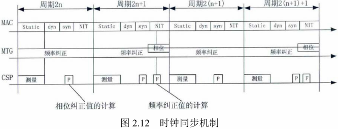
2.6 Clock Synchronization
If a TDMA-based communication protocol is used, access to the communication medium is controlled in the time domain. Therefore, it is crucial for each node to maintain time synchronization. The clocks of all nodes must be synchronized, and the maximum deviation (precision) must be within a specified range, which is a prerequisite for achieving clock synchronization.
Clock deviation can be divided into phase and frequency deviations. Phase deviation is the absolute difference between two clocks at a specific time. Frequency deviation is the change in phase deviation over time, reflecting the variation of phase deviation at a specific time.
FlexRay employs a comprehensive approach that implements both phase correction and frequency correction, involving two main processes: Maximum Time Tick Generation (MTG) and Clock Synchronization Calculation (CSP). MTG controls the initial values of time slots, i.e., the cycle counter and the maximum clock tick counter, and corrects them. CSP primarily initializes the start of a communication cycle, measures and stores deviation values, and calculates phase and frequency correction values.
Phase correction is executed only in the NIT segment of odd communication cycles, and it ends before the start of the next communication cycle. The phase correction value indicates the number of micro ticks to be added to the NIT phase correction segment, and its value is determined by the clock synchronization algorithm, which may be negative. The calculation of the phase correction value occurs within each cycle, but the correction is only applied at the end of odd communication cycles.
In frequency correction, measurements from two communication cycles are required. The difference between these measurements reflects the variation in clock deviation for each communication cycle. It is typically used to calculate the correction value at the end of two cycles. This correction value is used in the subsequent two communication cycles.
To conserve resources, some nodes enter a “sleep mode” when not in operation. When these nodes need to work again, they must be “woken up”. The host can transmit a wake-up mode on the communication channel, and the host processor and communication controller are powered on only after the node receives the wake-up symbol.
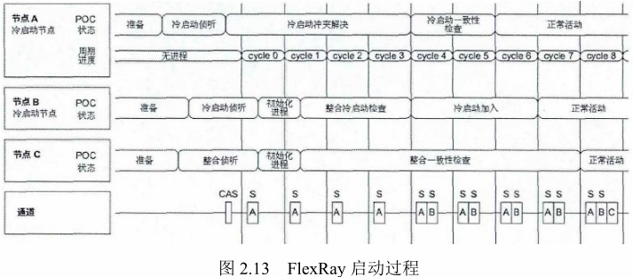
Before executing the communication startup, the entire cluster needs to be awakened. The startup of nodes needs to be synchronized across all channels. The initial behavior of a startup process is called a cold start. The nodes capable of initiating a start frame are limited and are referred to as cold start nodes. Within a cluster consisting of at least three nodes, at least three nodes must be configured as cold start nodes. Among the cold start nodes, the node that actively initiates messages in the cluster is called the leading cold start node, while the other cold start nodes are referred to as following cold start nodes.
When a node is awakened and completes initialization, it can enter the startup program after receiving the corresponding host control command. Non-cold start nodes wait until they receive and recognize at least two communicating cold start nodes. Meanwhile, cold start nodes monitor both communication channels to determine if other nodes are transmitting. When it is detected that no transmission is occurring on the communication channel, that node becomes the leading cold start node.
The cold start attempt begins with a Collision Avoidance Symbol (CAS), and only the cold start nodes transmitting CAS can transmit frames during the first four cycles. The leading cold start node first sends unformatted symbols (a certain number of invalid bits) on both channels and then initiates the cluster. After sending the unformatted symbols, the leading cold start node starts the clock for that node and enters the first communication cycle. Following cold start nodes can receive messages sent by the leading cold start node, and upon recognizing the messages, they confirm the time slot positions of the messages sent by the leading cold start node. They then wait for the next communication cycle, and upon receiving the second message, they start their clocks. Based on the timing of the two messages, they measure and calculate the frequency correction value to bring the following cold start nodes as close as possible to the time reference of the leading cold start node. To minimize errors, cold start nodes must wait for two communication cycles before transmission. During this time, other cold start nodes can continue to receive messages from the leading cold start node and any completed cluster cold start nodes.
From the fifth cycle onward, the remaining cold start nodes begin transmitting start frames. The leading cold start node receives all messages from the other cold start nodes within the fifth and sixth cycles and simultaneously performs clock corrections. If no faults occur during this process, and the cold start nodes receive at least one valid start frame message pair, the leading cold start node completes the startup phase and enters normal operating status.
Non-cold start nodes first listen to the communication channel and receive the information frames transmitted on the channel. If they receive an information frame transmitted on the channel, they begin attempting to integrate into the startup nodes. Within the next two cycles, non-cold start nodes must identify at least two cold start nodes that send startup frames and synchronize with their progress. If they cannot meet these conditions, non-cold start nodes will exit the startup process. After receiving at least two consecutive pairs of dual-cycle startup frames from cold start nodes, non-cold start nodes enter normal operating status. Non-cold start nodes enter normal operating status two cycles later than the leading cold start node.
The following figure describes the correct startup process, where A is the leading cold start node, B is the following cold start node, and C is the non-cold start node.
3.1 FlexRay Bus Applications in BMW Models
(1) Overview of FlexRay Bus Applications
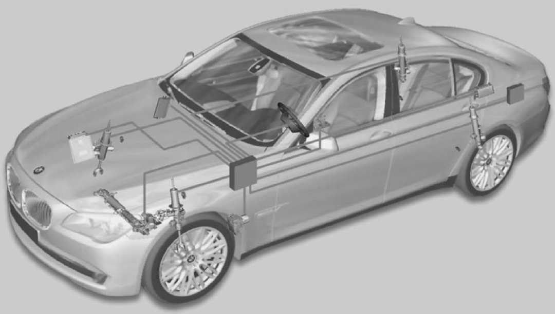
In the BMW F01/F02 series, the FlexRay bus system enables cross-system networking of the vehicle dynamics management system and engine management system. At the same time, FlexRay serves as the comprehensive main bus system for the vehicle dynamics management system (Figure 3.1), with the central gateway module connecting different bus systems to FlexRay (Figure 3.2).
Figure 3.1 FlexRay is the comprehensive main bus system for the vehicle dynamics management system
Figure 3.2 The central gateway module (ZGM) connects different bus systems to FlexRay
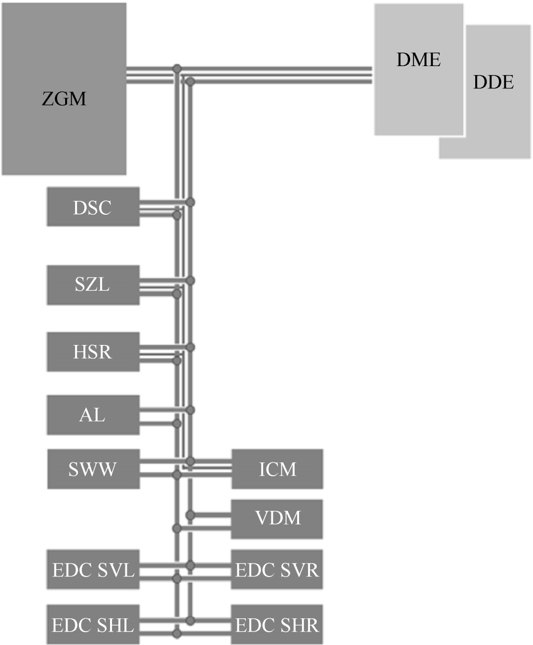
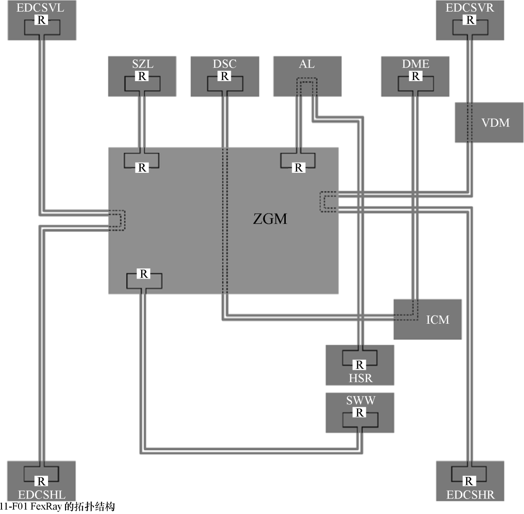
The topology of the FlexRay bus system in the F01/F02 models is shown in Figure 3.3. Depending on the vehicle configuration, the ZGM has one or two star connectors, each with four bus drivers. The bus drivers transmit the control unit data to the central gateway module (ZGM) via the communication controller. Depending on the terminal form of the FlexRay control unit, the bus drivers connect to these control units in two ways.
Figure 3.3 Topology of the FlexRay bus system in the F01/F02 models
The arbitration layer contains an arbitration network, which forms the backbone of FlexRay media arbitration. In the static segment, the arbitration network consists of continuous time intervals called static slots; in the dynamic segment, it consists of continuous time intervals called minislots.
The arbitration network layer is built on top of a macro tick layer composed of macro ticks. The time of each local macro tick is an integer multiple of the time of a micro tick. The assigned macro tick edges are called action points. Action points are specific moments when transmission starts and ends.
The micro tick layer is composed of micro ticks. Micro ticks are time units derived from the external oscillator clock of the communication controller, selectively using a frequency divider. Micro ticks are special units in the controller, and their timing may vary among different controllers. The local time interval size within the node is a micro tick.
2.6 Clock Synchronization
If a TDMA-based communication protocol is used, access to the communication medium is controlled in the time domain. Therefore, it is crucial for each node to maintain time synchronization. The clocks of all nodes must be synchronized, and the maximum deviation (precision) must be within a specified range, which is a prerequisite for achieving clock synchronization.
Clock deviation can be divided into phase and frequency deviations. Phase deviation is the absolute difference between two clocks at a specific time. Frequency deviation is the change in phase deviation over time, reflecting the variation of phase deviation at a specific time.
FlexRay employs a comprehensive approach that implements both phase correction and frequency correction, involving two main processes: Maximum Time Tick Generation (MTG) and Clock Synchronization Calculation (CSP). MTG controls the initial values of time slots, i.e., the cycle counter and the maximum clock tick counter, and corrects them. CSP primarily initializes the start of a communication cycle, measures and stores deviation values, and calculates phase and frequency correction values.
Phase correction is executed only in the NIT segment of odd communication cycles, and it ends before the start of the next communication cycle. The phase correction value indicates the number of micro ticks to be added to the NIT phase correction segment, and its value is determined by the clock synchronization algorithm, which may be negative. The calculation of the phase correction value occurs within each cycle, but the correction is only applied at the end of odd communication cycles.
In frequency correction, measurements from two communication cycles are required. The difference between these measurements reflects the variation in clock deviation for each communication cycle. It is typically used to calculate the correction value at the end of two cycles. This correction value is used in the subsequent two communication cycles.
To conserve resources, some nodes enter a “sleep mode” when not in operation. When these nodes need to work again, they must be “woken up”. The host can transmit a wake-up mode on the communication channel, and the host processor and communication controller are powered on only after the node receives the wake-up symbol.
Before executing the communication startup, the entire cluster needs to be awakened. The startup of nodes needs to be synchronized across all channels. The initial behavior of a startup process is called a cold start. The nodes capable of initiating a start frame are limited and are referred to as cold start nodes. Within a cluster consisting of at least three nodes, at least three nodes must be configured as cold start nodes. Among the cold start nodes, the node that actively initiates messages in the cluster is called the leading cold start node, while the other cold start nodes are referred to as following cold start nodes.
When a node is awakened and completes initialization, it can enter the startup program after receiving the corresponding host control command. Non-cold start nodes wait until they receive and recognize at least two communicating cold start nodes. Meanwhile, cold start nodes monitor both communication channels to determine if other nodes are transmitting. When it is detected that no transmission is occurring on the communication channel, that node becomes the leading cold start node.
The cold start attempt begins with a Collision Avoidance Symbol (CAS), and only the cold start nodes transmitting CAS can transmit frames during the first four cycles. The leading cold start node first sends unformatted symbols (a certain number of invalid bits) on both channels and then initiates the cluster. After sending the unformatted symbols, the leading cold start node starts the clock for that node and enters the first communication cycle. Following cold start nodes can receive messages sent by the leading cold start node, and upon recognizing the messages, they confirm the time slot positions of the messages sent by the leading cold start node. They then wait for the next communication cycle, and upon receiving the second message, they start their clocks. Based on the timing of the two messages, they measure and calculate the frequency correction value to bring the following cold start nodes as close as possible to the time reference of the leading cold start node. To minimize errors, cold start nodes must wait for two communication cycles before transmission. During this time, other cold start nodes can continue to receive messages from the leading cold start node and any completed cluster cold start nodes.
From the fifth cycle onward, the remaining cold start nodes begin transmitting start frames. The leading cold start node receives all messages from the other cold start nodes within the fifth and sixth cycles and simultaneously performs clock corrections. If no faults occur during this process, and the cold start nodes receive at least one valid start frame message pair, the leading cold start node completes the startup phase and enters normal operating status.
Non-cold start nodes first listen to the communication channel and receive the information frames transmitted on the channel. If they receive an information frame transmitted on the channel, they begin attempting to integrate into the startup nodes. Within the next two cycles, non-cold start nodes must identify at least two cold start nodes that send startup frames and synchronize with their progress. If they cannot meet these conditions, non-cold start nodes will exit the startup process. After receiving at least two consecutive pairs of dual-cycle startup frames from cold start nodes, non-cold start nodes enter normal operating status. Non-cold start nodes enter normal operating status two cycles later than the leading cold start node.
The following figure describes the correct startup process, where A is the leading cold start node, B is the following cold start node, and C is the non-cold start node.
3.1 FlexRay Bus Applications in BMW Models
(1) Overview of FlexRay Bus Applications
In the BMW F01/F02 series, the FlexRay bus system enables cross-system networking of the vehicle dynamics management system and engine management system. At the same time, FlexRay serves as the comprehensive main bus system for the vehicle dynamics management system (Figure 3.1), with the central gateway module connecting different bus systems to FlexRay (Figure 3.2).
Figure 3.1 FlexRay is the comprehensive main bus system for the vehicle dynamics management system
Figure 3.2 The central gateway module (ZGM) connects different bus systems to FlexRay
The topology of the FlexRay bus system in the F01/F02 models is shown in Figure 3.3. Depending on the vehicle configuration, the ZGM has one or two star connectors, each with four bus drivers. The bus drivers transmit the control unit data to the central gateway module (ZGM) via the communication controller. Depending on the terminal form of the FlexRay control unit, the bus drivers connect to these control units in two ways.
Figure 3.3 Topology of the FlexRay bus system in the F01/F02 models
AL—Active Steering System BD—Bus Driver DME—Digital Engine Management System DSC—Dynamic Stability Control System EDCSHL—Left Rear Electronic Dampening Control System Satellite Control Unit EDCSHR—Right Rear Electronic Dampening Control System Satellite Control Unit EDCSVL—Left Front Electronic Dampening Control System Satellite Control Unit EDCSVR—Right Front Electronic Dampening Control System Satellite Control Unit HSR—Rear Axle Side Slip Control System ICM—Integrated Chassis Management System SZL—Steering Column Switch Center VDM—Vertical Dynamics Management System ZGM—Central Gateway Module
(2) Terminal Resistor Settings
Like most bus systems, to avoid signal reflections on the lines, terminal resistors are also used at both ends of the data lines on FlexRay (as bus terminals). The resistance values of these terminal resistors are determined by the data transmission rate and wire length. Terminal resistors are located within each control unit.
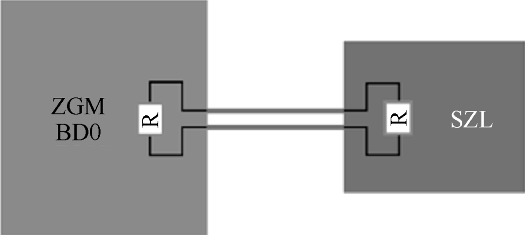
If only one control unit is connected to a bus driver (for example, SZL connected to bus driver BDO), then each bus driver and control unit interface has one terminal resistor (Figure 3.4). This connection method of the central gateway module is called a “terminating node terminal.”
Figure 3.4 Terminal resistor inside a terminating node terminal
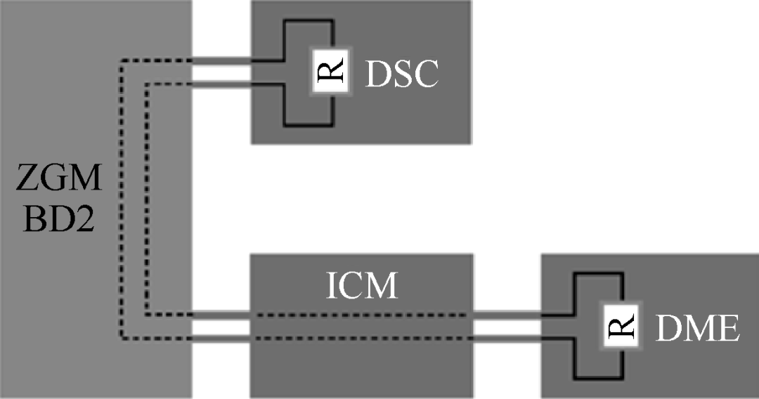
If the interface on the control unit is not a physical terminating node (for example, IEC, ICM, and DME on bus driver BD2), but forms a loop, then terminal resistors must be set inside the two components at each end of the total line path (Figure 3.5).
Figure 3.5 Setting of FlexRay terminal resistors forming a loop
This connection method is used for both the central gateway module and some control units. However, the control units forming a loop also use a “non-terminating node terminal” to obtain data. Due to the limitations of the resistance/capacitor circuit of this terminal form, it cannot be checked through measurement technology at the control unit plug. When measuring (without current) the FlexRay bus to determine the wire or terminal resistor, vehicle circuit diagrams must be used.
Disclaimer:Source from the internet, copyright belongs to the original author, and the opinions in the text are for sharing and communication only, not representing the position of this public account. If there are any copyright issues, please let us know, and we will handle them promptly.

Newly Launched Cloud Courses
1. Power Battery System CAE Simulation Technology (1-6)
2. Multi-Sensor Information Fusion Technology (1-3)
3. Analysis of Core Technologies of Nissan Series Hybrid (1-16)
4. HybridPower System Development Advanced Technology (1-5)
5. Power Battery Module Group Technology(1-5)
Video courses can be accessed on the official websitewww.auttra.com or click the button below“Read the original text” to enter the public account to learn.


Intelligent Electric Vehicle Development System and Project Management
Key Technologies for Software-Defined Vehicles
Architectural Design of High Voltage Systems for Vehicles and Safety Key Technologies
Innovative Design Methods for Intelligent Vehicle HMI
ISO26262 Functional Safety Software and Hardware Design and Testing
Architecture and Testing of Intelligent Driving Systems
Building Models Compliant with AUTOSAR Standards in MATLAB Environment(1-5)
Development and Design of Onboard Ethernet
Development and Design of Electric Drive Systems and Drive Motors for New Energy Vehicles
Development and Design of Vehicle Thermal Management
Thermal Management Design of Power Batteries in 23 Lectures(Lecture 1)
Thermal Management Simulation Analysis of Power Batteries in 20 Lectures(Lecture 1)
Simplification of SCDM Stamped Cold Plates
Configuration of Power Systems and Control of Driving Functions
Control of Hybrid Power Electric Drive Systems
Onboard Ethernet Protocol Architecture Design(1-5)
How to Build Models Compliant with AUTOSAR Standards on MATLAB Platform(1-5)
Development and Design of Onboard Chargers(1-3)
48V Overall Design Process(1-3)
Whole Vehicle EMC Testing(Upper and Lower)
CNA Remote Refresh and Diagnosis(1-6)
Design of Hybrid and Electric Vehicle Drive Systems (Upper)(Lower)
Plug-in Hybrid (PHEV) System Architecture
Pure Electric Drive System Architecture
Learn about open classes, video coursesDetails and Viewing
↙Click the bottom left to read the original text