“ State machines are a key tool in embedded system development, allowing complex logic to be broken down into clear states and transition rules. This article introduces the core elements, five implementation patterns, and code examples, along with recommendations for pattern selection to help developers efficiently create reliable embedded systems.“
01
—
Introduction to State Machines
State machines are a mathematical model or design pattern that describes the behavior of a system transitioning between different states. By defining a finite set of states and the transition rules between them, they make the behavior of complex systems clear and manageable. Mastering the core elements of state machines is fundamental to successful embedded system design.
The core elements of a state machine include:
State:
The stable operating mode or behavior phase of the system at a given moment. The system can only be in one state at any time, such as “idle”, “running”, “fault”, or “sleep” in an embedded device. Each state corresponds to specific behaviors or functions.
Event:
An external or internal signal that triggers a state transition. It is important to note that only valid signals with specific triggering conditions constitute events. For example: “button pressed” (not all button signals), “sensor data changes exceed threshold” (not all data changes), “timer timeout”, etc. Events are the catalysts for state transitions, determining how the system moves from one state to another.
Action:
Operations performed during a state transition or while in a specific state. Actions can be categorized into entry actions (executed when entering a state), exit actions (executed when leaving a state), and internal actions (executed while the state is active).
Transition:
The process of switching from one state to another due to an event occurring, following predefined transition rules. The transition rule must satisfy the complete expression of “current state + triggering event + optional condition → next state + associated action”, for example: “idle state + button pressed event + button duration ≥ 10ms (after debouncing) → sampling state + initialize ADC action”.
State machines are mainly divided into Moore Machines and Mealy Machines:
In a Moore machine, the output is determined solely by the current state, such as a traffic light where the “red light state” consistently outputs a stop signal, and the “green light state” consistently outputs a go signal, resulting in stable output logic. In a Mealy machine, the output is determined by both the current state and input events, such as an automatic vending machine where in the “waiting for payment state”, inserting sufficient coins outputs a product signal, while insufficient coins output a prompt to add more money, allowing for dynamic adaptability based on different events.
02
—
Common Implementation Patterns of Embedded State Machines
There are various implementation patterns for state machines in embedded systems, each suitable for different scenarios and characteristics. Here are five mainstream implementation patterns:
1. Switch-Case Statement Method
All states are defined using an enumeration type, and branching is handled in a large switch statement based on the current state and event. This is the most basic and intuitive implementation method, suitable for scenarios with few states and simple logic. Its advantages include simplicity of implementation, straightforward code, and ease of understanding; however, its disadvantages include poor maintainability and scalability due to all states and transition logic being stacked together.
2. State Table Driven Method
This method uses a predefined array of structures (state table) to describe the state transition rules, with each table entry containing “current state, event, next state, action to execute”. This approach separates data (transition rules) from logic (execution code), resulting in a clear structure and better scalability. The downside is that it requires additional storage for the state table, which can become large if there are many states or events.
3. Function Pointer Method
Each state is represented by an independent function, which handles all possible events and is responsible for state transitions (by changing function pointers in the global or context). The advantage of this method is high cohesion, as the behavior of each state is encapsulated in its respective function, resulting in a high degree of modularity; however, the use of function pointers requires caution, as it may affect code readability.
4. Object-Oriented State Pattern
For embedded systems that support C++, an object-oriented design pattern can be adopted. An abstract state base class (interface) is defined, and a derived class is created for each specific state to implement specific behaviors. The context class holds a pointer to the current state object. The advantage of this pattern is that it adheres to the open-closed principle, allowing new states to be added without modifying existing code, and it has good encapsulation; however, it requires C++ support, and each state is an instance of a class, which introduces some memory and runtime overhead.
5. Hierarchical State Machine (HSM)
This pattern supports nested state management for complex logic, allowing states to have parent-child relationships, where child states can inherit behaviors and transitions from parent states. This pattern simplifies the management of complex state systems and improves reusability, making it particularly suitable for very complex systems.
03
—
State Machine Code Implementation
1. Switch-Case Statement Method
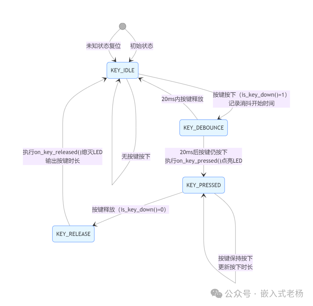
The following code implements a key debounce state machine with four states: KEY_IDLE (idle), KEY_DEBOUNCE (debouncing), KEY_PRESSED (pressed), and KEY_RELEASE (released), completing key press detection, 20ms debouncing, LED control, and key duration calculation, with the main loop polling the state machine every 10ms.
#include "stm32f1xx_hal.h"
#include <stdio.h>// Pin definitions
#define KEY_PIN GPIO_PIN_0
#define KEY_PORT GPIOA
#define LED_PIN GPIO_PIN_13
#define LED_PORT GPIOC// State definitions
typedef enum {
    KEY_IDLE,      // Key idle state
    KEY_DEBOUNCE,  // Key debounce state
    KEY_PRESSED,   // Key pressed state
    KEY_RELEASE    // Key released state
} KeyState_t;// Global variables
KeyState_t key_state = KEY_IDLE;
uint32_t debounce_time = 0;
uint32_t key_press_duration = 0;// Function declarations
void SystemClock_Config(void);
void MX_GPIO_Init(void);
void Error_Handler(void);// Actual key reading function (STM32 HAL library)
int is_key_down(void) {
    return (HAL_GPIO_ReadPin(KEY_PORT, KEY_PIN) == GPIO_PIN_RESET) ? 1 : 0;
}// Actual system time function (STM32 HAL library)
uint32_t get_millis(void) {
    return HAL_GetTick();
}// Key pressed handling function
void on_key_pressed(void) {
    printf("Key pressed!\n");
    HAL_GPIO_WritePin(LED_PORT, LED_PIN, GPIO_PIN_SET);
}// Key released handling function
void on_key_released(void) {
    printf("Key released! Duration: %lums\n", key_press_duration);
    HAL_GPIO_WritePin(LED_PORT, LED_PIN, GPIO_PIN_RESET);
    key_press_duration = 0;
}// State machine handling function
void key_fsm(void) {
    switch (key_state) {
        case KEY_IDLE:
            if (is_key_down()) {
                key_state = KEY_DEBOUNCE;
                debounce_time = get_millis();
                printf("State: IDLE -> DEBOUNCE\n");
            }
            break;
        case KEY_DEBOUNCE:
            if (get_millis() - debounce_time > 20) {
                if (is_key_down()) {
                    key_state = KEY_PRESSED;
                    on_key_pressed();
                    printf("State: DEBOUNCE -> PRESSED\n");
                } else {
                    key_state = KEY_IDLE;
                    printf("State: DEBOUNCE -> IDLE\n");
                }
            }
            break;
        case KEY_PRESSED:
            key_press_duration = get_millis() - debounce_time;
            if (!is_key_down()) {
                key_state = KEY_RELEASE;
                printf("State: PRESSED -> RELEASE\n");
            }
            break;
        case KEY_RELEASE:
            on_key_released();
            key_state = KEY_IDLE;
            printf("State: RELEASE -> IDLE\n");
            break;
        default:
            // Handle unknown state for robustness
            key_state = KEY_IDLE;
            printf("Unknown state! Reset to IDLE\n");
            break;
    }
}// Main function
int main(void) {
    // Initialization
    ......
    printf("Starting key state machine demo...\n");
    while (1) {
        key_fsm();
        HAL_Delay(10); // 10ms delay to reduce CPU usage
    }
    return 0;
}
The state transition diagram for the above code is shown below:
2. State Table Driven Method
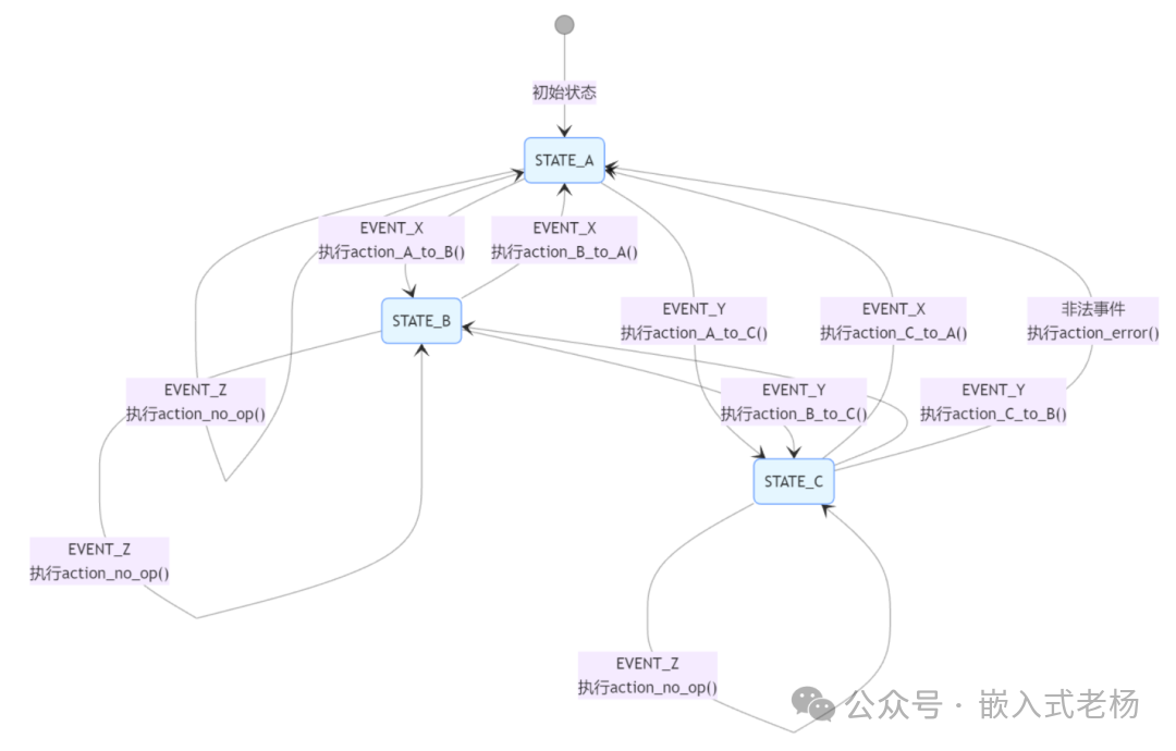
The following code defines three states: STATE_A, STATE_B, STATE_C, and three events: EVENT_X, EVENT_Y, EVENT_Z. It specifies the jump targets and actions to be executed upon receiving events in different states through a state table, including boundary checks to handle illegal states or events (resetting to STATE_A). The main function simulates an event sequence to test the state machine flow.
#include <stdio.h>
#include <stdint.h>// State and event definitions (using uint8_t type to save memory)
typedef enum : uint8_t {
    STATE_A,
    STATE_B,
    STATE_C,
    STATE_COUNT
} State;
typedef enum : uint8_t {
    EVENT_X,
    EVENT_Y,
    EVENT_Z,
    EVENT_COUNT
} Event;// State table entry structure
typedef struct {
    State next_state;
    void (*action)(void);
} TransitionEntry;// Action functions
void action_A_to_B(void) { printf("Transition from A to B\n"); }
void action_A_to_C(void) { printf("Transition from A to C\n"); }
void action_B_to_A(void) { printf("Transition from B to A\n"); }
void action_B_to_C(void) { printf("Transition from B to C\n"); }
void action_C_to_A(void) { printf("Transition from C to A\n"); }
void action_C_to_B(void) { printf("Transition from C to B\n"); }
void action_no_op(void) { /* No operation */ }
void action_error(void) { printf("Error: Invalid state/event!\n"); }// State table definition
const TransitionEntry state_table[STATE_COUNT][EVENT_COUNT] = {
    [STATE_A] = {
        [EVENT_X] = { .next_state = STATE_B, .action = action_A_to_B },
        [EVENT_Y] = { .next_state = STATE_C, .action = action_A_to_C },
        [EVENT_Z] = { .next_state = STATE_A, .action = action_no_op }
    },
    [STATE_B] = {
        [EVENT_X] = { .next_state = STATE_A, .action = action_B_to_A },
        [EVENT_Y] = { .next_state = STATE_C, .action = action_B_to_C },
        [EVENT_Z] = { .next_state = STATE_B, .action = action_no_op }
    },
    [STATE_C] = {
        [EVENT_X] = { .next_state = STATE_A, .action = action_C_to_A },
        [EVENT_Y] = { .next_state = STATE_B, .action = action_C_to_B },
        [EVENT_Z] = { .next_state = STATE_C, .action = action_no_op }
    }
};
// Current state
State current_state = STATE_A;// Event processing function (with boundary checks)
void process_event(Event event) {
    // Boundary check: prevent array out of bounds
    if (current_state >= STATE_COUNT || event >= EVENT_COUNT) {
        action_error();
        current_state = STATE_A; // Reset to initial state
        return;
    }
    TransitionEntry entry = state_table[current_state][event];
    if (entry.action != NULL) {
        entry.action();
    }
    current_state = entry.next_state;
    printf("Current state: %d\n", current_state);
}// Main function
int main(void) {
    printf("Starting state table demo...\n");
    printf("Initial state: %d\n", current_state);
    // Simulate event sequence
    Event events[] = { EVENT_X, EVENT_Y, EVENT_Z, EVENT_X, 5 }; // Last illegal event test
    for (int i = 0; i < sizeof(events)/sizeof(events[0]); i++) {
        printf("Processing event: %d\n", events[i]);
        process_event(events[i]);
    }
    return 0;
}
The state transition diagram for the above code is shown below:
3. Function Pointer Method
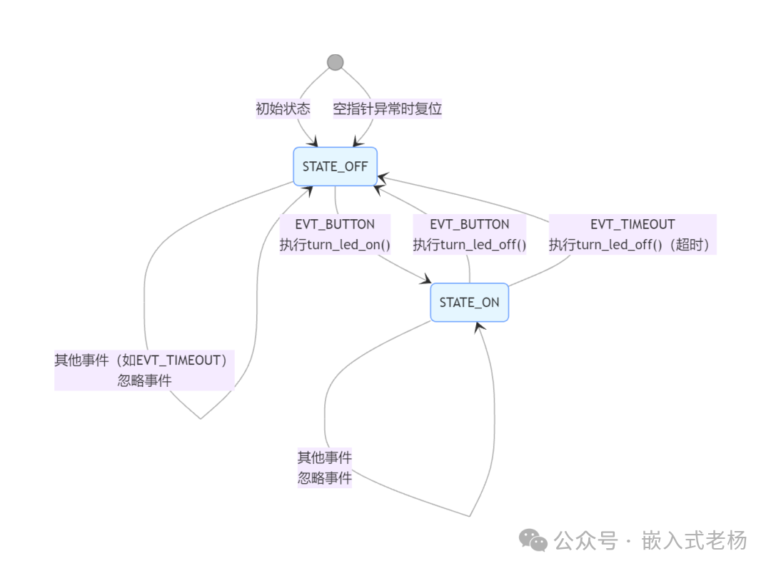
The following code implements an LED state machine using function pointers, including two states: STATE_OFF (off) and STATE_ON (on), which can respond to EVT_BUTTON (button) and EVT_TIMEOUT (timeout) events: initially in the off state, a button event triggers the LED to light up and switches to the on state; in the on state, either a button or timeout event triggers the LED to turn off and return to the off state, also including null pointer exception handling (resetting to the off state). The main function simulates an event sequence to test the state machine flow.
#include <stdio.h>
#include <stdint.h>// Event type definition
typedef enum { EVT_BUTTON, EVT_TIMEOUT, EVT_MAX } EventType;// State function prototype
typedef void (*state_handler_t)(EventType evt);// State function declarations
void state_off(EventType evt);
void state_on(EventType evt);
void handle_error(void);// Global variable
state_handler_t current_state = &state_off;
uint32_t light_on_time = 0;// Action functions
void turn_led_on(void) { printf("LED turned ON\n"); }
void turn_led_off(void) { printf("LED turned OFF\n"); }
void handle_error(void) { printf("Error handled\n"); }// State function implementation
void state_off(EventType evt) {
switch (evt) {
case EVT_BUTTON:
turn_led_on();
current_state = &state_on;
light_on_time = 0;
printf("State: OFF -> ON\n");
break;
default:
printf("State OFF: Ignored event %d\n", evt);
break;
}
}
void state_on(EventType evt) {
switch (evt) {
case EVT_BUTTON:
turn_led_off();
current_state = &state_off;
printf("State: ON -> OFF\n");
break;
case EVT_TIMEOUT:
turn_led_off();
current_state = &state_off;
printf("State: ON -> OFF (Timeout)\n");
break;
default:
printf("State ON: Ignored event %d\n", evt);
break;
}
}// State machine execution function (with null pointer check)
void state_machine_run(EventType evt) {
if (current_state != NULL) {
current_state(evt);
} else {
// Handle null pointer exception
handle_error();
current_state = &state_off; // Reset to initial state
}
}// Simulated event generation
EventType get_next_event(void) {
static int count = 0;
EventType events[] = { EVT_BUTTON, EVT_TIMEOUT, EVT_BUTTON, EVT_BUTTON };
return events[count++ % 4];}// Main function
int main(void) {
printf("Starting function pointer state machine demo...\n");
// Simulate execution
for (int i = 0; i < 5; i++) {
EventType evt = get_next_event();
printf("Processing event: %d\n", evt);
state_machine_run(evt);
// Simulate delay
for (int j = 0; j < 1000000; j++);
}
// Test null pointer recovery
printf("\nTesting error recovery...\n");
current_state = NULL;
state_machine_run(EVT_BUTTON);
return 0;
}The state transition diagram for the above code is shown below:
4. Object-Oriented State Pattern
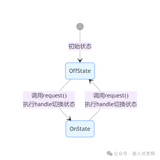
The following code adopts the object-oriented state pattern, defining an abstract interface for State and specific state classes OffState (off) and OnState (on), with a Context class managing the current state. When calling the request method of the Context, it triggers the handle method of the current state, achieving state transitions (off → on → off cycle) and outputting state information.
#include <iostream>// State interface
class State {
public:
virtual void handle(class Context* context) = 0;
virtual ~State() {}
};
// Concrete state class: Off state
class OffState : public State {
public:
void handle(Context* context) override;
};
// Concrete state class: On state
class OnState : public State {
public:
void handle(Context* context) override;
};
// Context class
class Context {
private:
State* current_state_;
public:
Context() : current_state_(new OffState()) {}
~Context() { delete current_state_; // Manual memory release
}
void set_state(State* new_state) {
if (current_state_ != nullptr)
delete current_state_;
current_state_ = new_state;
}
void request() {
if (current_state_ != nullptr) {
current_state_->handle(this);
}
}
void display_state(const std::string& state_name) {
std::cout << "Current state: " << state_name << std::endl;
}
};
// State handling implementation
void OffState::handle(Context* context) {
context->display_state("Off");
std::cout << "Switching to On state" << std::endl;
context->set_state(new OnState());
}
void OnState::handle(Context* context) {
context->display_state("On");
std::cout << "Switching to Off state" << std::endl;
context->set_state(new OffState());
}// Main function
int main() {
std::cout << "Starting object-oriented state pattern demo..." << std::endl;
Context context;
// Simulate several state transitions
for (int i = 0; i < 3; i++) {
context.request();
}
return 0;
}The state transition diagram for the above code is shown below:
5. Hierarchical State Machine
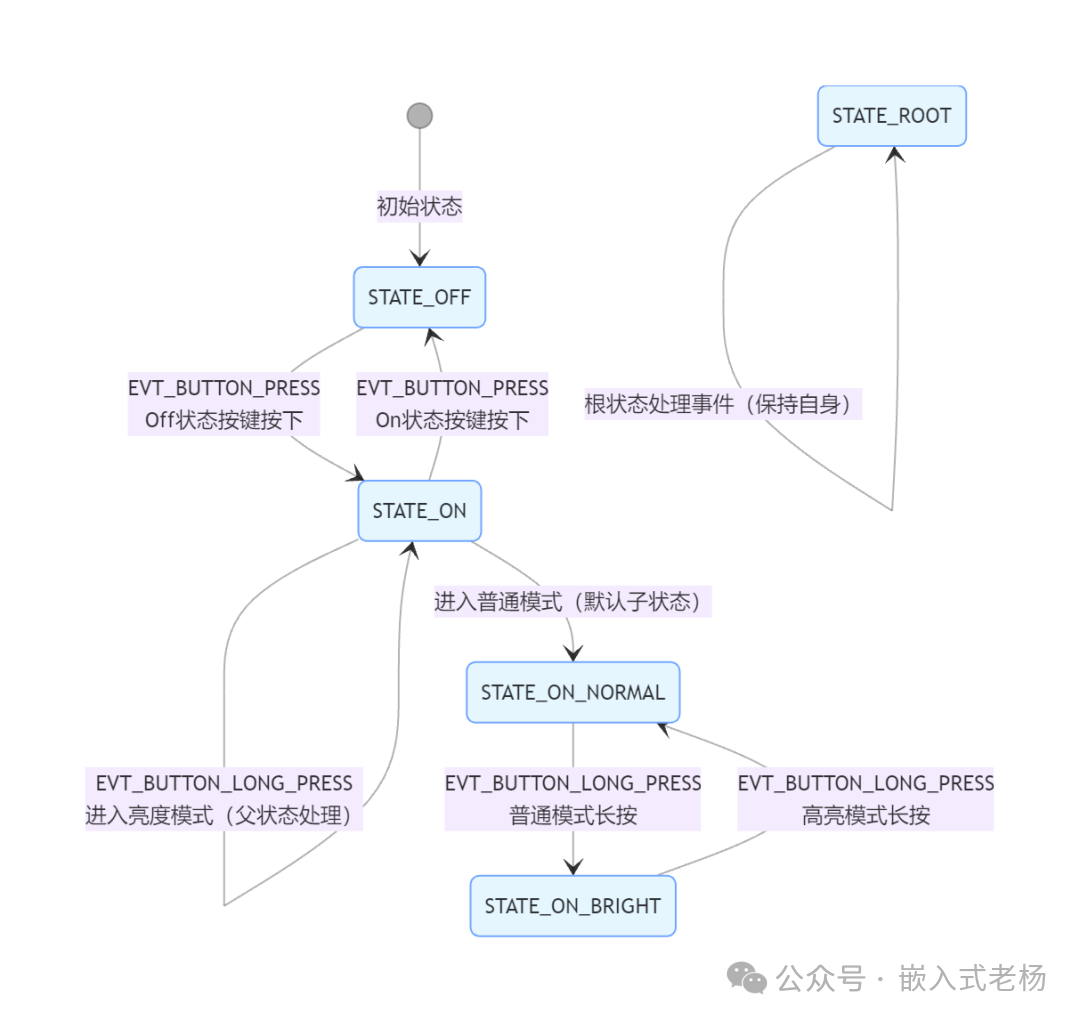
The following code implements a hierarchical state machine with a root state, on/off states, and normal/highlighted sub-states. The hsm_dispatch_event function allows the parent state to handle events first and recursively pass them down, responding to button press, long press, and other events to achieve state transitions. The main function simulates an event sequence to test the state flow.
#include <stdio.h>
#include <stdint.h>// State definitions
typedef enum {
STATE_ROOT,
STATE_ON,
STATE_OFF,
STATE_ON_NORMAL,
STATE_ON_BRIGHT,
STATE_COUNT
} StateType;// Event definitions
typedef enum {
EVT_BUTTON_PRESS,
EVT_BUTTON_LONG_PRESS,
EVT_TIMEOUT,
EVT_MAX
} EventType;// State handling function prototype
typedef StateType (*state_handler_t)(EventType evt);// Define parent-child state mapping table (clarifying hierarchy)
const StateType parent_state_map[STATE_COUNT] = {
[STATE_ROOT] = STATE_ROOT, // Root state has no parent
[STATE_ON] = STATE_ROOT, // ON's parent state is root
[STATE_OFF] = STATE_ROOT, // OFF's parent state is root
[STATE_ON_NORMAL] = STATE_ON, // NORMAL's parent state is ON
[STATE_ON_BRIGHT] = STATE_ON // BRIGHT's parent state is ON
};
// State handling functions
StateType root_state(EventType evt) {
printf("Root state handling event: %d\n", evt);
return STATE_ROOT; // Maintain current state
}
StateType on_state(EventType evt) {
switch (evt) {
case EVT_BUTTON_PRESS:
printf("On state: Button press -> switching to Off\n");
return STATE_OFF;
case EVT_BUTTON_LONG_PRESS:
printf("On state: Long press -> entering brightness mode\n");
return STATE_ON;
default:
printf("On state: Passing event to root\n");
return STATE_ON; // Maintain current state
}
}
StateType off_state(EventType evt) {
switch (evt) {
case EVT_BUTTON_PRESS:
printf("Off state: Button press -> switching to On\n");
return STATE_ON;
default:
printf("Off state: Passing event to root\n");
return STATE_OFF; // Maintain current state
}
}
StateType on_normal_state(EventType evt) {
switch (evt) {
case EVT_BUTTON_LONG_PRESS:
printf("Normal mode: Long press -> switching to Bright mode\n");
return STATE_ON_BRIGHT;
default:
// No need to handle, event will be passed to parent
return STATE_ON_NORMAL;
}
}
StateType on_bright_state(EventType evt) {
switch (evt) {
case EVT_BUTTON_LONG_PRESS:
printf("Bright mode: Long press -> switching to Normal mode\n");
return STATE_ON_NORMAL;
default:
// No need to handle, event will be passed to parent
return STATE_ON_BRIGHT;
}
}// State table
state_handler_t state_table[STATE_COUNT] = {
[STATE_ROOT] = root_state,
[STATE_ON] = on_state,
[STATE_OFF] = off_state,
[STATE_ON_NORMAL] = on_normal_state,
[STATE_ON_BRIGHT] = on_bright_state
};
// Event dispatch function (parent state handles first, recursive passing)
void hsm_dispatch_event(StateType* current_state, EventType evt) {
// 1. Call the current state's handling function first, get new state
StateType new_state = state_table[*current_state](evt);
// 2. Update current state
*current_state = new_state;
// 3. If current state is not root, pass to parent state
StateType parent = parent_state_map[*current_state];
if (parent != *current_state) { // Avoid recursive root state
hsm_dispatch_event(&parent, evt);
}
}// State machine context
typedef struct {
StateType current_state;
uint32_t timer;
} StateMachine;// Main function
int main(void) {
printf("Starting hierarchical state machine demo...\n");
StateMachine fsm = { .current_state = STATE_OFF };
// Test event sequence
EventType events[] = { EVT_BUTTON_PRESS, EVT_BUTTON_LONG_PRESS, EVT_BUTTON_PRESS };
for (int i = 0; i < sizeof(events)/sizeof(events[0]); i++) {
printf("\nProcessing event: %d\n", events[i]);
hsm_dispatch_event(&fsm.current_state, events[i]);
printf("Final state after event: %d\n", fsm.current_state);
}
return 0;
}The state transition diagram for the above code is shown below:
04
—
How to Choose a State Machine Implementation Pattern
Choosing the appropriate state machine implementation pattern requires a comprehensive consideration of system complexity, resource constraints, development team skills, and long-term maintenance needs. Here are the key selection factors:
|
Consideration Factor |
Recommended Pattern |
Reasons and Details |
|
System Complexity |
Simple System: Switch-Case Method |
Few states (≤3), few events (≤2), simple logic, minimal changes |
|
Medium Complexity: State Table Driven / Function Pointer Method |
More states and events (state count × event count ≤ 32), clear rules, requires good scalability |
|
|
Complex System: Object-Oriented Pattern / Hierarchical State Machine |
Many states and events (state count × event count > 32), hierarchical needs, requires high maintainability and scalability |
|
|
Resource Constraints |
Severely Limited: Switch-Case Method |
Extremely limited memory (<1KB RAM), high execution efficiency required |
|
Moderate Resources: State Table Driven / Function Pointer Method |
Moderate memory (1-4KB RAM), acceptable memory overhead for state table (when states/events are few) |
|
|
Abundant Resources: Object-Oriented Pattern |
Ample memory (>4KB RAM), acceptable overhead of object-oriented design |
|
|
Real-Time Requirements |
High Real-Time: Switch-Case / Function Pointer Method |
High execution efficiency, predictable timing |
|
General Real-Time: State Table Driven Method |
Table lookup incurs slight overhead |
|
|
Soft Real-Time: Object-Oriented Pattern |
Virtual function calls incur some overhead |
|
|
Team Skills |
Mainly C Language: Switch-Case / State Table |
Team is familiar with C language and has rich embedded experience |
|
Proficient in C++: Object-Oriented Pattern |
Team is proficient in C++ and object-oriented design |
|
|
Long-Term Maintenance |
Stable Changes: Switch-Case Method |
Stable requirements, low likelihood of changes in the future |
|
Frequent Changes: State Table Driven / Object-Oriented Pattern |
Requires frequent addition of new states or modification of transition rules |
1. Communication Mechanism Selection
State machines need to communicate with the external environment, and common communication mechanisms include:
Polling:
Continuously checking conditions or flags, simple to implement but high CPU usage, suitable for simple systems (no RTOS, main loop polling).
Event Triggered:
Asynchronous notifications through interrupts or callbacks, fast response and low resource usage, suitable for event-driven systems (e.g., interrupt-triggered state transitions).
Blocking Wait:
Thread blocks waiting for events to occur, saving CPU but may introduce thread switching overhead, suitable for multi-threaded IO operations (requires RTOS support).
Message Queue:
Asynchronous communication through thread-safe queues, decoupling producer and consumer, suitable for multi-task environments (complex systems, multiple event sources).
2. Adaptation of Different State Machine Patterns to Communication Mechanisms:
Switch-Case / Function Pointer Method:
In the interrupt service function (ISR), only “mark the event flag”, and in the main loop, check the flag and call the state machine for processing.
State Table Driven Method:
In the ISR, “add the event to the event queue”, and in the main loop, take events from the queue and match the state table.
Object-Oriented Pattern:
In the ISR, “call the event enqueue interface of Context”, and in the main loop, call context->request() to process events.
05
—
Conclusion
The state machine pattern is a powerful tool in embedded system development, capable of breaking down complex logic into finite states and clear transition rules, significantly enhancing code readability and maintainability. Choosing the appropriate pattern based on actual project needs is crucial:
Simple systems (few states, simple logic, minimal changes): Prefer the Switch-Case statement method for its simplicity and low resource usage.
Medium complexity systems (more states and events, clear rules): Recommend the state table driven method or function pointer state method, balancing complexity and performance, and easy to extend.
Complex systems (C++ environment, high maintainability requirements): Choose the object-oriented state pattern or hierarchical state machine, although they incur higher resource overhead, they provide the best encapsulation and scalability.
Multi-task environments: Use message queue mechanisms combined with RTOS for inter-task communication.
Previous Articles:
Low Power GPIO Modes
Embedded System Firmware Programming Methods
FreeRTOS Task Priority Configuration Principles
Introduction to FreeRTOS Tasks
Types of Diodes, Working Principles, and Applications
MCU Low Power Modes
Wi-Fi 7 is here! Five times faster than Wi-Fi 6, your network is about to take off!
Recommended book for beginners in electronic design (includes electronic version)
Microcontroller AD Sampling Filtering Algorithm