There are two types of power supplies for PLC systems: external power supply and internal power supply.The external power supply is used to drive PLC output devices (loads) and provide input signals, also known as user power supply. The external power supply for the same PLC may have multiple specifications. The capacity and performance of the external power supply are determined by the output devices and the PLC’s input circuit. Since the PLC’s I/O circuits have filtering and isolation functions, the external power supply has little impact on PLC performance. Therefore, the requirements for the external power supply are not high.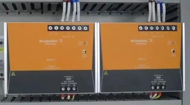 The internal power supply is the working power supply for the PLC, meaning it powers the internal circuits of the PLC. Its quality directly affects the reliability of the PLC. Therefore, to ensure the normal operation of the PLC, there are high requirements for the internal power supply. Generally, the internal power supply of a PLC uses a switch-mode power supply or a primary-side regulated power supply with a low-pass filter.
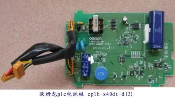 In environments with strong interference or high reliability requirements, a shielded isolation transformer should be used to power the PLC system. An LC filter circuit can also be connected in series on the secondary side of the isolation transformer. Additionally, the following issues should be noted during installation:(1) It is best to use twisted pair connections between the isolation transformer and the PLC and I/O power supply to control common-mode interference;(2) The power lines of the system should be sufficiently thick to reduce voltage drops caused by the startup of large-capacity devices;(3) When using an external DC power supply for the PLC input circuit, it is best to use a regulated power supply to ensure correct input signals; otherwise, the PLC may receive incorrect signals.
02
Avoid Strong Interference Sources
(1) Power lines, control lines, and the PLC’s power and I/O lines should be wired separately. Twisted pair connections should be used between the isolation transformer and the PLC and I/O. The PLC’s I/O lines and high-power lines should be routed separately; if they must be in the same cable tray, AC and DC lines should be bundled separately. If conditions allow, it is best to route them in separate trays to maximize the distance and minimize interference.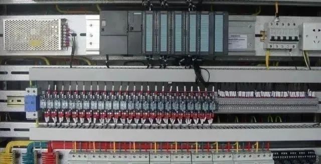 (2) The PLC should be kept away from strong interference sources such as welding machines, high-power silicon rectifiers, and large power equipment, and should not be installed in the same switch cabinet as high-voltage electrical devices. Inside the cabinet, the PLC should be kept away from power lines (the distance between them should be greater than 200mm). Inductive loads, such as large relays and contactor coils, installed in the same cabinet as the PLC should have parallel RC snubber circuits.(3) AC output lines and DC output lines should not use the same cable; output lines should be kept as far away as possible from high-voltage lines and power lines to avoid parallel routing.
03
I/O Wiring Requirements
(1) It is best to separate the wiring for PLC inputs and outputs, and to separate digital and analog signals. Shielded cables should be used for transmitting analog signals, with the shield grounded at one end or both ends, and the grounding resistance should be less than 1/10 of the shield resistance.(2) Input Wiring ● Input wiring should generally not be too long. However, if the environmental interference is low and the voltage drop is small, the input wiring can be slightly longer. ● Input/output lines should not use the same cable; they should be separated. ● It is preferable to use normally open contacts connected to the input terminals to ensure that the ladder diagram corresponds with the relay schematic for easier reading.  (3) Output Connections ● Output connections are divided into independent outputs and common outputs. Different types and voltage levels of output voltage can be used in different groups. However, outputs within the same group can only use the same type and voltage level of power supply.● Since the PLC’s output components are encapsulated on the printed circuit board and connected to the terminal block, short-circuiting the load connected to the output components will damage the printed circuit board. ● When using relay outputs, the size of the inductive load will affect the lifespan of the relay; therefore, inductive loads should be chosen wisely, or an isolation relay should be added. ● PLC output loads may generate interference, so measures should be taken to control it, such as using flyback diodes for DC outputs, RC snubber circuits for AC outputs, and bypass resistors for transistor and bidirectional thyristor outputs.
04
Select the Correct Grounding Point
Good grounding is an important condition for ensuring the reliable operation of the PLC, as it can prevent accidental voltage surges. The purpose of grounding usually has two aspects: one for safety and the other to suppress interference. A well-designed grounding system is one of the important measures to enhance the PLC control system’s resistance to electromagnetic interference. The grounding system of the PLC control system includes system ground, shield ground, AC ground, and protective ground.The confusion in the grounding system can cause interference in the PLC system mainly due to uneven potential distribution among various grounding points, resulting in ground potential differences and ground loop currents that affect normal system operation. For example, the cable shield must be grounded at one point; if both ends A and B of the cable shield are grounded, there will be a ground potential difference, and current will flow through the shield. When abnormal conditions occur, such as lightning strikes, the ground current will be even greater.Additionally, the shield, grounding wire, and earth may form a closed loop, and under the influence of a changing magnetic field, induced currents may appear within the shield, interfering with the signal circuit through coupling between the shield and the core wire. If the system ground is confused with other grounding treatments, the resulting ground loop may create uneven potential distribution on the ground wire, affecting the normal operation of the PLC’s logic and analog circuits. The PLC’s logical voltage interference tolerance is low, and disturbances in the logical ground potential distribution can easily affect the PLC’s logical operations and data storage, causing data confusion, program runaway, or system crashes. The distribution of analog ground potential will lead to decreased measurement accuracy, causing serious distortion and malfunctions in signal measurement and control.● Safety Ground or Power Ground Connect the grounding terminal of the power line and the cabinet body to safety ground. If there is a power leak or the cabinet is live, the safety ground will direct it underground, preventing harm to individuals. ● System Ground The PLC controller is grounded to be at the same potential as the controlled devices, known as system ground. The grounding resistance should not exceed 4Ω, and generally, the PLC equipment system ground should be connected to the negative terminal of the power supply in the control cabinet, serving as the control system ground. ● Signal and Shield Ground Generally, signal lines must have a unique reference ground. In cases where shielded cables may produce conductive interference, they should also be grounded uniquely at the site or control room to prevent forming a “ground loop.” When grounding the signal source, the shield should be grounded on the signal side; if not grounded, it should be grounded on the PLC side. If there are joints in the signal line, the shield should be securely connected and insulated, avoiding multiple grounding points; when connecting multiple measurement signal shielded twisted pairs to a multi-core shielded cable, each shield should be well connected and insulated, with a suitable single-point grounding location chosen.
05
Interference Suppression for Frequency Converters
Interference handling for frequency converters generally includes the following methods:  Using an isolation transformer mainly addresses conducted interference from the power supply, which can block most of the conducted interference before it reaches the isolation transformer. Using filters, which have strong anti-interference capabilities, can also prevent the device’s own interference from being conducted to the power supply, and some filters also have surge voltage absorption functions. Using output reactors, adding AC reactors between the frequency converter and the motor mainly reduces electromagnetic radiation generated during energy transmission from the frequency converter, which can affect the normal operation of other devices.