Smart cars are a large collection of IoT devices, and the general electronic systems are shown in the figure below. Each electronic system uses a large number of electronic components.
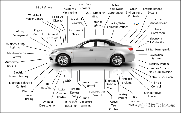
Smart cars not only include IVI and TBOX but also contain dozens of ECUs. Different modules focus on different aspects, and the chips used also vary significantly. IVI requires strong performance to provide information service capabilities and human-computer interaction capabilities, so it often uses many chips;
TBOX is not as complex as IVI, mainly undertaking communication tasks with the server, primarily using communication module chips; although individual ECU functions vary greatly due to their different roles, they mostly use MCUs.
Below are some introductory concepts, followed by demonstrations of how to extract firmware without chip removal from external Flash and MCUs in cars.
Basic Knowledge
Chip Packaging and Pin Definitions
Using a chip clip can achieve pin exposure for chip firmware extraction without removal for SOP, QFP packaging, while it is ineffective for QFN, BGA, and other packaging methods.
● SOP8/16
SOP (Small Out-Line Package) pins are led out from both sides of the package in a seagull wing shape (L shape), generally used for chips with fewer pins. SOP8/16 packaged Flash is commonly found in routers, cameras, and other IoT devices. The pins are either 8 or 16, and one corner has a small dot (each chip has a small dot, which indicates the first pin, and the following pins are arranged counterclockwise), and the model code generally starts with 24 or 25. The typical pin definition for SOP8/16 SPI Flash is as follows.
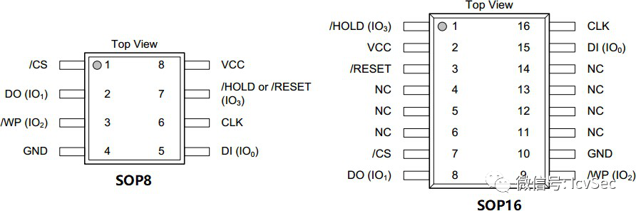
|
Pin |
Definition |
|
/CS |
Chip Select |
|
DO |
Data Output |
|
/WP |
Write Protect |
|
GND |
Ground |
|
VCC |
Power Supply Positive |
|
/HOLD |
Input Hold |
|
/RESET |
Reset |
|
CLK |
Clock |
|
DI |
Data Input |
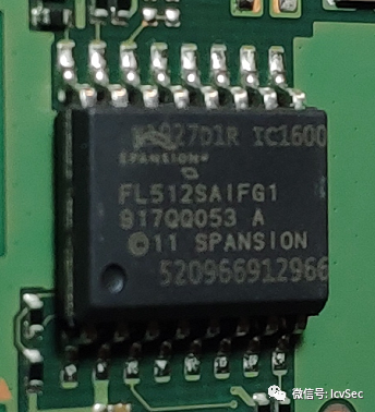
The Flash in a certain car machine shown below uses SOP16 packaging.
● QFP
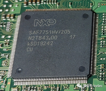
QFP (Plastic Quad Flat Package) pins are led out from four sides in a seagull wing (L) shape. The pin spacing is very small, and the pins are fine, generally used for large-scale or ultra-large-scale integrated circuits, with the number of pins usually over 64. In small IoT devices, it can serve as the main controller or co-processor. The radio chip in a certain car machine shown below uses QFP packaging.
This type of packaging has no fixed number of pins and no unified standard; generally, the manufacturer defines the pin definitions, which can be found in the chip manual.
● BGA
BGA (Ball Grid Array Package) I/O terminals are distributed in a grid format at the bottom of the package with circular or columnar solder points, offering a smaller size and better thermal and electrical performance. Since the I/O terminals are located under the package, extracting firmware requires using a BGA rework station to remove it for reading, which cannot achieve extraction without removal. BGA packaging is generally used for CPUs and large-capacity storage.
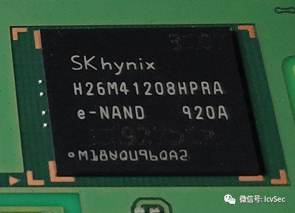
The above image shows a Flash with BGA packaging in a certain car machine, similar to QFP packaged chips, the pin definitions need to be referred to in the corresponding chip manual.
Chip Clips
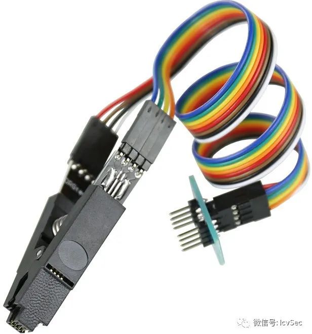
There are generally three types of clips used. The first type is the SOP8/16 pin clip, commonly used for extracting firmware from SPI flash; the second type is the universal chip test clip, often used for extracting firmware from SOP and QFP packaged chips or protocol analysis; the third and fourth types are ECU probes, mainly used for extracting firmware from automotive ECUs.
1. SOP8/16 pin clip
The SOP8/16 pin clip is mainly suitable for SOP8 and SOP16 packaged chips.
2. Universal chip test clip
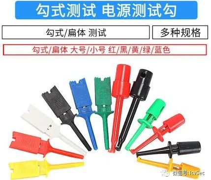
This type of hook is available in several varieties online; the type shown below is only suitable for chips with fewer pins, such as those using SOP8 packaging. The hook style is single hook, while the flat style is double hook. This type is relatively cheaper.
The following type of clip is finer and can be used for chips with more and finer pins, such as QFP packaged MCUs. This type of clip is generally more expensive than the previous one.
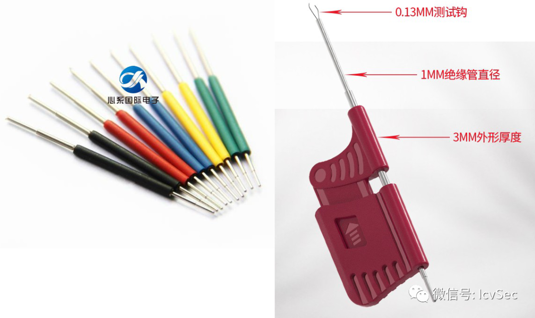
These clips are relatively small, and when needing to clip consecutive pins, there can be some difficulty, requiring repeated attempts. Additionally, due to the lack of support, they may pop off immediately after being clipped on; in such cases, an ECU general probe can be used to connect.
3. ECU universal probe
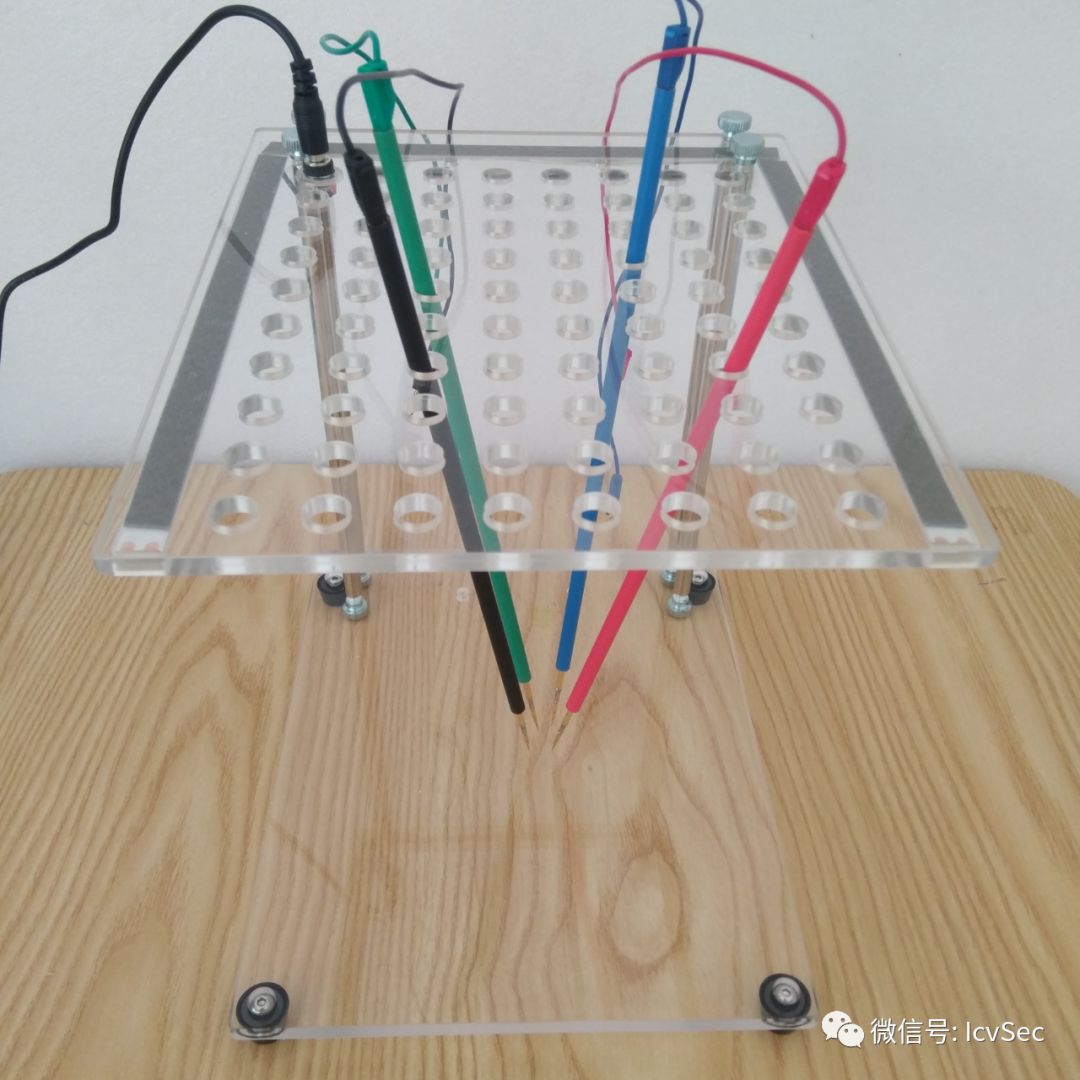
Commonly used in the automotive industry, it is an essential item for power tuning and car enthusiasts. Of course, other chips can also use it for firmware extraction. This type has a support structure, so you only need to place the probe on the corresponding chip pins during use.
4. ECU dedicated probe
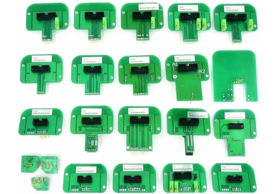
When performing BDM debugging on an ECU, a specific adapter is required to connect some metal contacts on the ECU circuit board with the reading and writing device. This type of probe is also referred to as a BDM adapter.
ECU Rewriting Tools
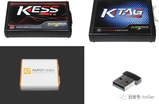
Reading and writing to the engine ECU (Engine Control Unit) requires ECU rewriting tools. The rewriting tools developed in the automotive power tuning field are relatively mature, with well-known names like HP Tuners, PCMFlash, Alientech (KTAG & KESS), Autotuner, etc.
The field of ECU power tuning is relatively closed, and there is very little information available on the internet regarding this area. The limited information is also focused on power tuning and does not involve information security.
ECU Debugging Modes
ECU rewriting tools have four working modes: Bench, BDM/JTAG, Boot, and OBD modes.
Bench: Working bench mode, does not require opening the computer board to connect to the boot points, directly reads and writes to the pin insertion points.
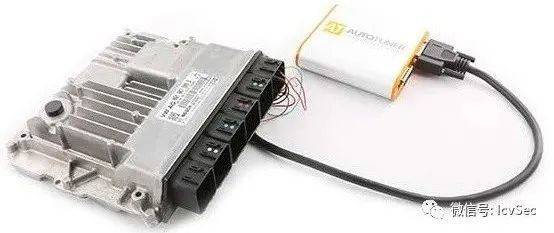
BDM/JTAG: Connects the metal contacts on the ECU circuit board with the reading and writing device through dedicated pins to perform read and write operations.
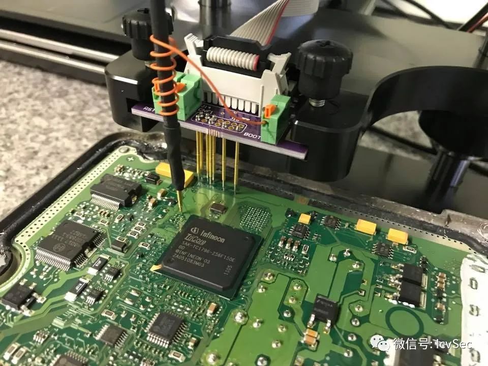
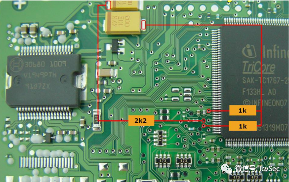
Boot: A special BDM method, in addition to needing to connect some metal contacts on the ECU circuit board, it also requires powering the ECU and connecting some resistors, while the steps for reading and writing the ECU are stricter than BDM.
The connection diagram for EDC17C46 Boot mode is as follows.
OBD: For certain specific ECU models, the first rewrite cannot be done directly through OBD; it requires a Bench and Boot unlock first before read and write operations can be performed through OBD.
Extracting Firmware from Flash
Reading Flash without removal generally involves reading SOP8 packaged SPI Flash, using the SOP8/16 pin clip is more convenient. The required software and hardware for extraction are as follows.
● Software
flashrom: flashrom is an open-source, cross-platform programming tool that provides support for many chips and programmers, used to identify, read, write, verify, and erase various Flash chips.
● Hardware
Test Clip: SOP16 pin clip, detailed introduction above.
Programmer: CH341A programmer/Raspberry Pi/CJMCU FT232H, etc. (any one of these)
In the firmware extraction without chip removal, I used a Raspberry Pi; here I will demonstrate using FT232H.
1. Install flashrom
Install directly using apt.
sudo apt-get install flashrom2. Wiring
First, locate the Flash on the car machine; according to the chip marking, the Flash is Spansion’s FL512SAIFG1, with a capacity of 64MB.
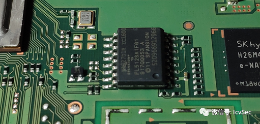
Find the pin definitions in the chip manual.
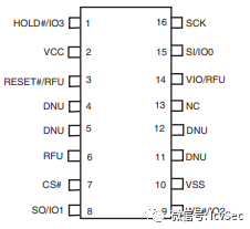
Finally, connect according to the table below.
|
FT232H |
SPI FLASH |
|
AD0(SCK) |
SCK |
|
AD1(MOSI) |
MOSI |
|
AD2(MISO) |
MISO |
|
AD3(/CS) |
/CS |
|
VCC 3.3V |
VCC 3.3V(+/HOLD or /RESET,/WP) |
|
GND |
GND |
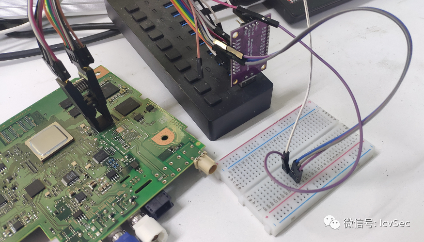
The effect of the connected wiring is shown below.
3. Extraction
After connecting the wires, use flashrom to extract the firmware. The -p option specifies the device type to use; here, the SPI interface of the Raspberry Pi is used, and the read/write speed is set; the -r option specifies the path to save after reading; the option to write back to the flash from the file is -w. The firmware was successfully extracted and saved to the current directory as the file spi_dump.bin.
root@ul00:~# flashrom -p ft2232_spi:type=232H -r spi_dump.bin flashrom v1.2 on Linux 5.3.0-kali2-amd64 (x86_64)flashrom is free software, get the source code at https://flashrom.org
Using clock_gettime for delay loops (clk_id: 1, resolution: 1ns). Found Spansion flash chip "S25FL512S" (65535 kB, SPI) on linux_spi.Reading flash... done.
Extracting Firmware from MCU
Extracting firmware from Flash is more common, but in some cases, the firmware is not stored on the external Flash but in the internal Flash of the MCU. In this case, it is necessary to extract the firmware through the debugging interface (SWD/JTAG, etc.) and can also perform dynamic debugging.
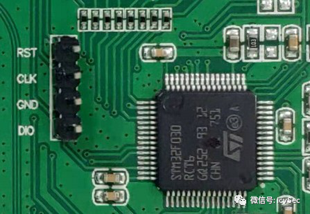
To extract firmware from the MCU, first, find the debugging interface based on the chip manual. In some cases, the debugging interface may be exposed. The following image shows a smart device I have studied, which has the SWD debugging interface exposed on the board.
However, as hardware manufacturers pay more attention to security, the situation of exposing MCU debugging interfaces is becoming increasingly rare. When encountering this situation, one can try to operate directly on the chip pins. Below is a demonstration of using a chip test clip to extract the internal firmware from the MCU. The required software and hardware for extraction are as follows.
● Hardware
Test Clip: Universal chip test clip.
FT232H: A multifunctional USB to JTAG SWD/UART/FIFO SPI/I2C module. JLink, STLink, and other debuggers can also be used.
● Software
OpenOCD: OpenOCD (Open On-Chip Debugger) is an open-source on-chip debugger designed to provide debugging, system programming, and boundary scan capabilities for embedded devices, and can be used with GDB for dynamic debugging.
The following uses a certain car machine as an example to verify whether the debugging interface SWD is enabled by using the test clip through OpenOCD.
1. OpenOCD Installation and Simple Use
Install directly using apt:
sudo apt-get install openocdIf there are special requirements, source installation can also be performed. Some chip manufacturers have adapted OpenOCD, such as Nuvoton’s OpenOCD-Nuvoton.
OpenOCD requires two configuration files to run; the first is the configuration file for the debugger, and the second is the configuration file for the target chip.
openocd -f interface/ft232h-module-swd.cfg -f target/stm32f0x.cfgAfter OpenOCD runs, use telnet to connect to the local 4444 port to interact with the chip. After connecting, enter help to view the supported commands; different chips support different commands. Generally, the command for extracting firmware is dump_image.
GDB dynamic debugging listens on the local 3333 port, and after entering GDB, connect using target remote localhost:3333.
2. Wiring
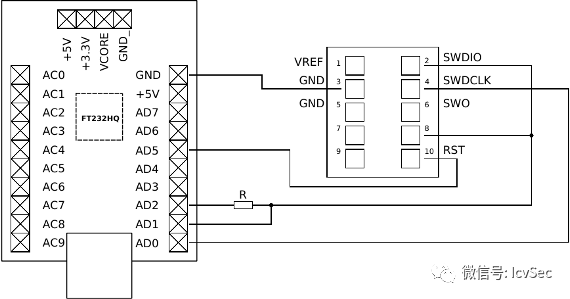
Find the corresponding chip manual based on the chip marking. In the manual, find the debugging method; this chip uses SWD for debugging. Locate the four pins: SWDIO, SWCLK, VSS, and RESET on the chip. Then, connect FT232H as shown in the figure below. Note that AD2 (DO) needs to be connected in series with a resistor, and then merged with AD1 (DI) to form SWDIO.
Finally, connect FT232H to the computer via USB; the connected image is shown below.
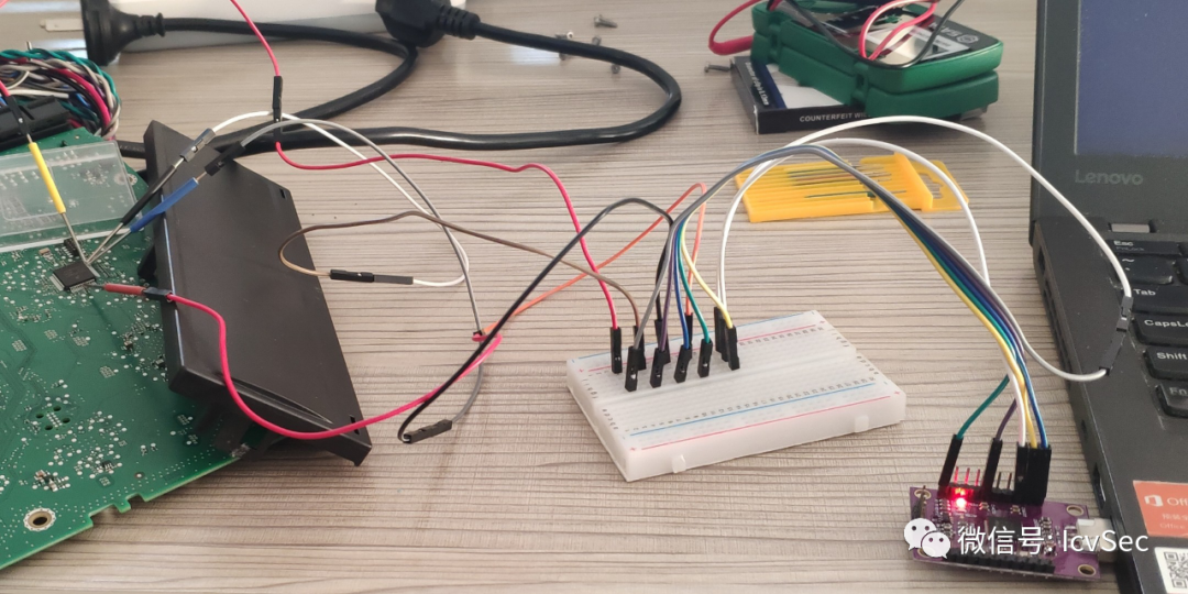
3. OpenOCD Connection, Verify SWD Enabled Status
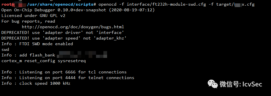
OpenOCD connection failed; the chip has enabled CRP protection. The test passed, and the car machine’s SWD is turned off by default during manufacturing.
Using ECU Rewriting Tools to Extract Firmware
Alientech’s KTAG and KESS are well-known in the industry and widely used in the automotive power tuning field. For those of us in information security, we can borrow advanced experience from this.
● KESS
KESS is an OBD computer ECU upgrade device that does not require disassembly.
● KTAG
KTAG is an ECU upgrade device that requires disassembly of the computer board to read and write programs.
KESS and KTAG can sometimes be used together; KESS OBD mode requires KTAG to unlock through MDB/BOOT mode. After unlocking, KESS can read and write through OBD.
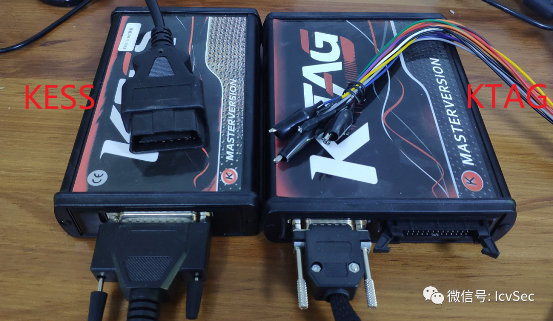
The following shows how to use KTAG to unlock and read firmware, mainly introducing the connection methods between ECU, KTAG, and the computer directly. There are many videos on YouTube, but these videos rarely introduce the physical connection part; I am writing this to help newcomers avoid some detours. The ECU being read is from an Audi S5, with the ECU model being Simos 8.10. This ECU supports BDM mode and OBD mode; initially, KESS cannot be used for reading and writing through OBD until unlocked by KTAG.
1. Determine ECU Model
Many ECU housings have model labels; common ones include Siemens Simos 8.x, Bosch MED 17.x, Bosch ME7.x.x, etc. The ECU label in the image below shows the model Simos 8.10.
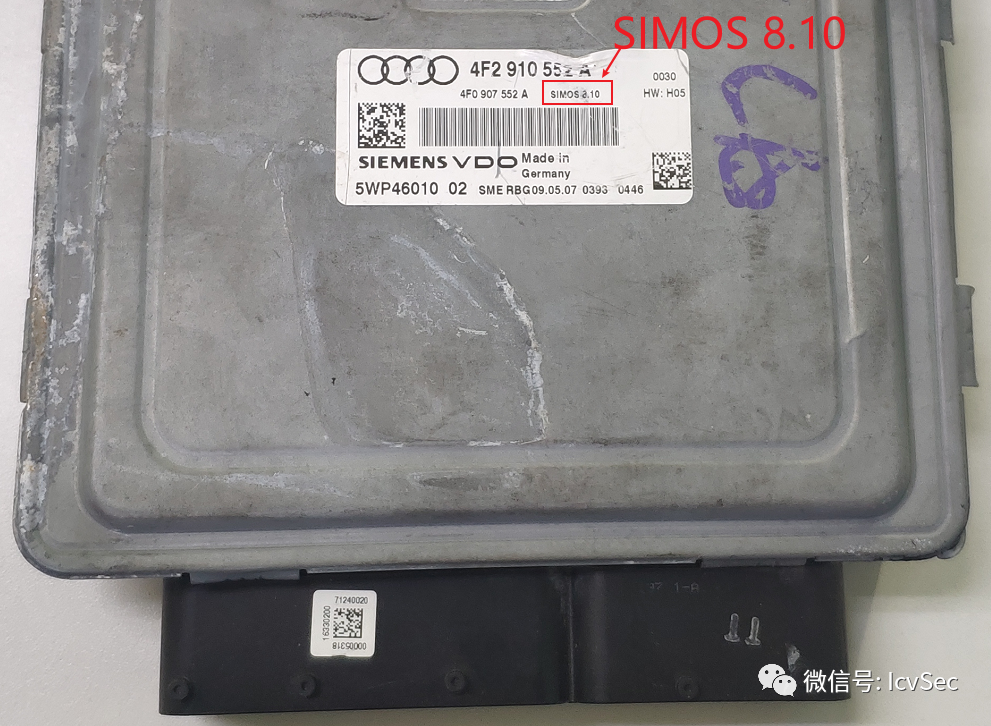
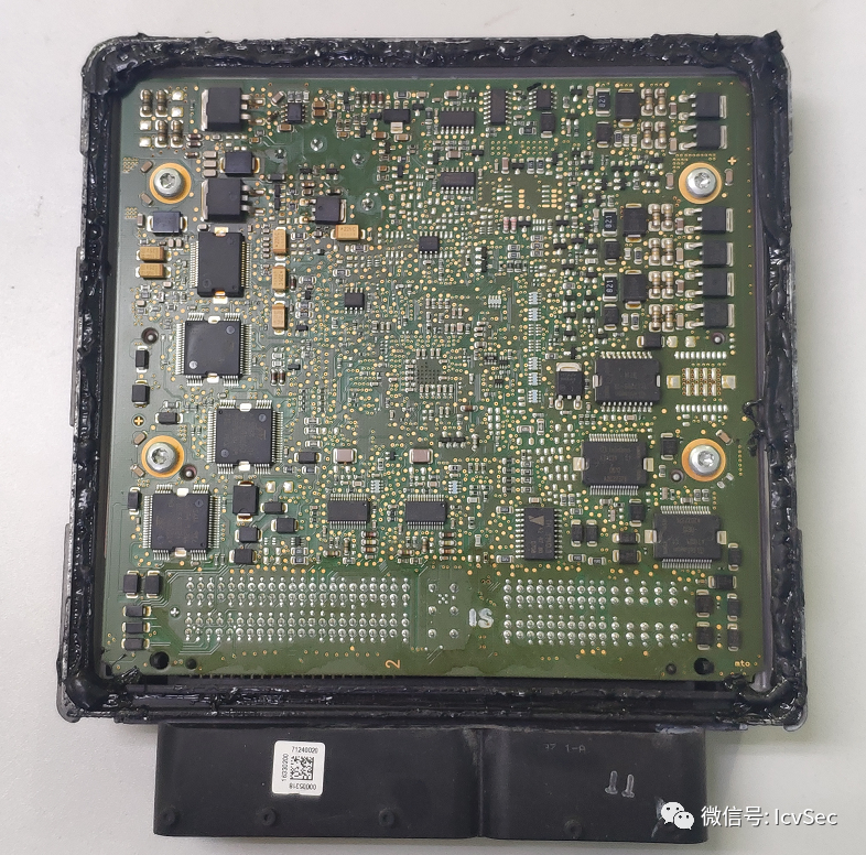
2. Disassemble ECU
It must be said that disassembling the ECU is quite difficult; the waterproof adhesive is particularly strong, and it is recommended to use a hot air gun to heat and remove it.
3. Wiring
Fortunately, there is documentation (Ksuite help document); otherwise, who knows how to connect BOOT and CNF.
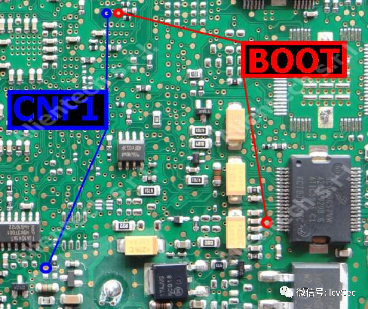
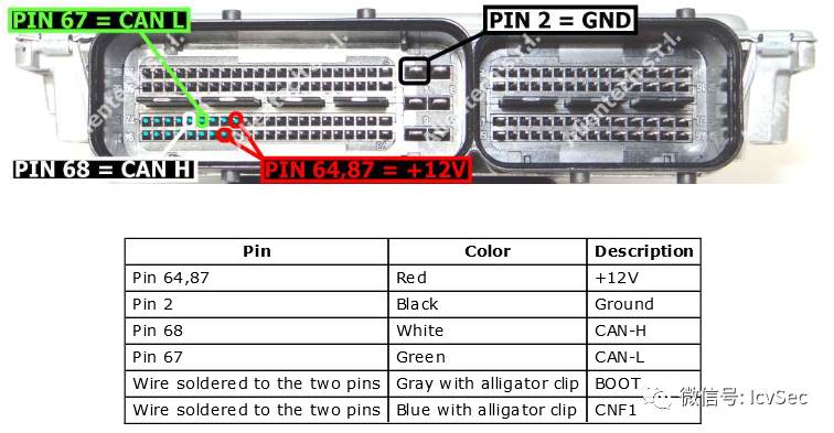
The pins in the above table need to be connected to the 14P600KT02 wiring harness; the color in the above table indicates the color of each wire in the 14P600KT02 wiring harness. Connect according to the table. Then, connect the 14P600KT02 to KTAG, and finally, use USB-B to connect KTAG to the computer.
4. Reading
Open the accompanying software Ksuite, first select the example car brand, such as Audi. Then select the model S5.
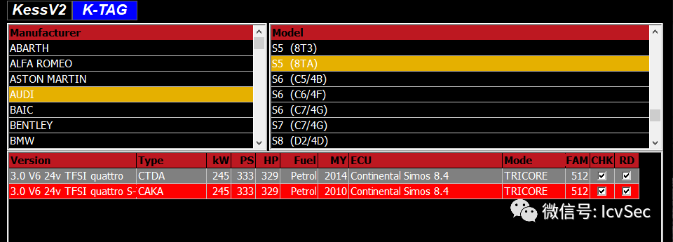
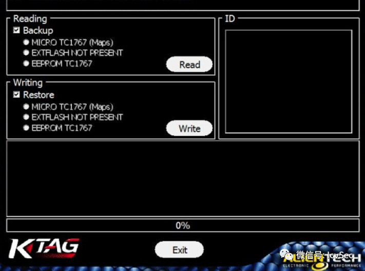
Then, select the objects to be exported from Backup in Reading, and finally click Read.
Original source: Automotive Information Security