Abstract
In response to the limited fault diagnosis and performance monitoring capabilities of the satellite Power Control Unit (PCU), a test design was conducted on a certain satellite’s power control unit, establishing an on-orbit fault diagnosis and performance monitoring system based on Built-In Test (BIT) technology. The BIT consists of 3 simulation boards and 1 core board, where the simulation boards can perform high-speed sampling of dozens of analog signals, and the core board runs fault diagnosis and performance monitoring algorithms, as well as handling data storage, data packaging, and communication tasks. The results of fault diagnosis and performance monitoring are sent to the communication interface after packaging. Verification experiments show that the system can accurately detect and locate faults in the PCU without affecting its normal operation, ensuring fast diagnosis speed, while also monitoring performance such as bus voltage ripple of the PCU.
Narrowly defined home decoration: refers to indoor decoration; it is considered from the perspective of beautification to make the indoor space more aesthetically pleasing;
Broadly defined home decoration: includes the transformation and renovation of indoor spaces; what we refer to as home decoration today is mostly the broad definition, which is a combination of indoor renovation and decoration.
Chinese citation format: Liu Xinjun, Zhang Donglai, Li Anshou, et al. Fault diagnosis and performance monitoring system for PCU based on BIT technology[J]. Application of Electronic Technique, 2019, 45(5): 34-37.English citation format: Liu Xinjun, Zhang Donglai, Li Anshou, et al. Fault diagnosis and performance monitoring system for PCU based on BIT technology[J]. Application of Electronic Technique, 2019, 45(5): 34-37.
0 Introduction
Currently, the satellite Power Control Unit (PCU) and performance monitoring are completed by ground systems based on telemetry data, which has limited diagnostic real-time capabilities and control capabilities, and some faults and performance cannot be detected. At the same time, most current on-orbit power controllers rarely consider the needs for fault diagnosis and performance monitoring, only providing simple health status information of the power module, unable to diagnose and locate specific faults, nor monitor performance such as bus voltage ripple. Therefore, the testability design work of power controllers still needs further improvement[1-3]. To address this issue, this paper conducts a testability design of the PCU[4-6], implementing on-orbit fault diagnosis and performance monitoring based on satellite Built-In Test (BIT) technology[7], greatly improving the efficiency and accuracy of PCU fault diagnosis, while monitoring PCU performance, laying a foundation for on-orbit maintenance and health management.
1 PCU Working Principle and Test Point Selection
1.1 PCU Working Principle
The PCU is the core device of the satellite power system, playing a role in regulating the power balance between the solar panels, batteries, and loads, and is responsible for providing stable primary bus power for the satellite and charging and discharging management functions for the batteries, which is an important guarantee for the stable operation of the satellite throughout its life cycle.
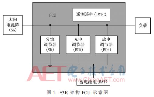
Figure 1 shows the composition diagram of the power system based on the S3R architecture. The system consists of solar panel arrays, battery packs, loads, and the PCU, where the PCU includes shunt regulators (SR), charge regulators (BCR), discharge regulators (BDR), and telemetry and remote control (TMTC). During sunlight periods, the PCU adjusts the solar panel array through the shunt regulator; when the load’s power demand is less than the output power of the solar panel array, the surplus energy charges the battery pack through the charge regulator. During shadow periods, it discharges the battery pack through the discharge regulator to provide a fully regulated primary bus for the entire satellite.
1.2 Test Point Selection
A certain satellite’s PCU adopts the S3R topology, consisting of 6 shunt regulators (SR), 2 charge regulators (BCR), and 2 discharge regulators (BDR).
The test points of the PCU are determined according to the following steps:
(1) Fault mode analysis. Conduct fault mode analysis on modules such as shunt regulators SR, charge regulators BCR, discharge regulators BDR, etc. The analysis reveals fault modes including common shunt faults in the shunt regulation circuit, common power supply faults in the shunt regulation circuit, no output from the discharge regulator, incorrect output current values from the discharge regulator, no output from the charge regulator, incorrect output current values from the charge regulator, and failure of constant voltage control in the charge regulator.
(2) Testability modeling. Based on fault mode analysis and fault propagation relationship analysis, use testability modeling software to establish a correlation model between faults and tests for the PCU. The test points related to these fault modes include the Main Error Amplifier (MEA) voltage, solar array sub-voltage, bus voltage, discharge regulator output current, charge regulator output current, and battery pack voltage.
(3) Consider performance monitoring needs. The performance to be monitored includes: bus voltage ripple, shunt regulator efficiency, discharge regulator efficiency, charge regulator efficiency, requiring test points for bus voltage, solar array sub-voltage, battery pack voltage, discharge regulator input-output current, and charge regulator input-output current.
(4) Test point optimization. Comprehensive consideration of fault diagnosis and performance monitoring needs, optimizing for fault detection rate and fault isolation rate, while considering the impact of test points on the original circuit, completing test point optimization. The final determined test points are shown in Table 1.
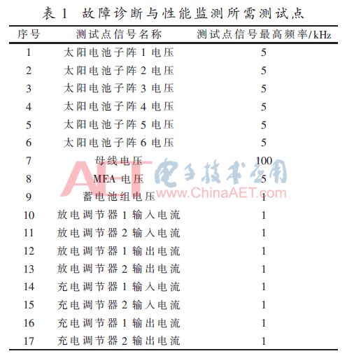
Compared to fault diagnosis based on telemetry data, the fault detection rate and fault isolation rate have greatly improved after adopting BIT technology. The improvement in fault detection rate and isolation rate mainly comes from two aspects: (1) Increase in test points. Some faults cannot be detected based on the original telemetry test points, and the BIT design adds test points to detect and locate these faults. (2) Increase in sampling frequency of test points. The original telemetry test point’s sampling frequency was too low, resulting in some faults being undetectable. The BIT design increased the sampling frequency, allowing for the detection and location of these faults.
2 System BIT Hardware and Software Implementation
2.1 BIT Hardware Implementation
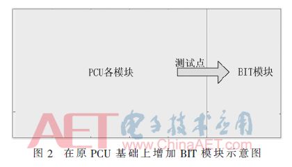
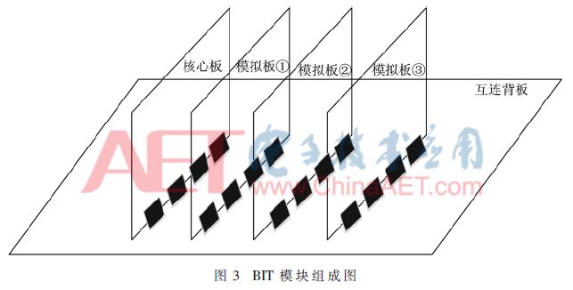
As shown in Figure 2, a BIT module was added based on the original PCU modules. The BIT module adopts a modular design, including 1 core board and 3 simulation boards, as shown in Figure 3. The core board is based on FPGA+ARM dual-core, used to run fault diagnosis algorithms and for communication; the simulation boards are high-speed sampling FPGAs responsible for sampling test points at different sampling frequencies; each simulation board and the core board are connected through a high-speed backplane. The fault diagnosis results and performance monitoring results of the BIT are transmitted to the 1553B communication interface.
2.2 BIT Software Implementation
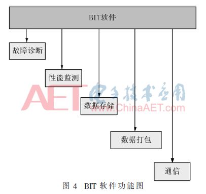
Software is written in the microprocessor circuit to complete fault diagnosis and performance monitoring. As shown in Figure 4, the BIT software includes fault diagnosis and performance monitoring tasks, specifically including fault diagnosis module, performance monitoring module, data storage module, data packaging and sending module, and communication module.
The fault diagnosis module utilizes the collected test point data to compare the differences between normal operating conditions and fault conditions. When the difference reaches a certain threshold or the logical state is opposite, it is considered that a fault has occurred.
The performance monitoring module uses sampled test points to monitor the performance of key components of the PCU, including bus voltage ripple, shunt efficiency, charge efficiency, and discharge efficiency. It is important to note that due to different operating modes, not all power modules are always in operational status; performance metrics should be evaluated and calculated when the modules are in operational status.
The data storage module stores fault diagnosis results, performance monitoring data, and fault-related data. The fault-related data can be taken from the test point data related to the detected fault within 10 ms before and after detection. If the data exceeds storage space, it will overwrite the earliest stored data.
The data packaging module packages the fault diagnosis results, performance monitoring data, and fault-related data.
The communication module sends the packaged information to the 1553B communication interface.
3 Experimental Verification
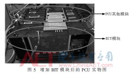
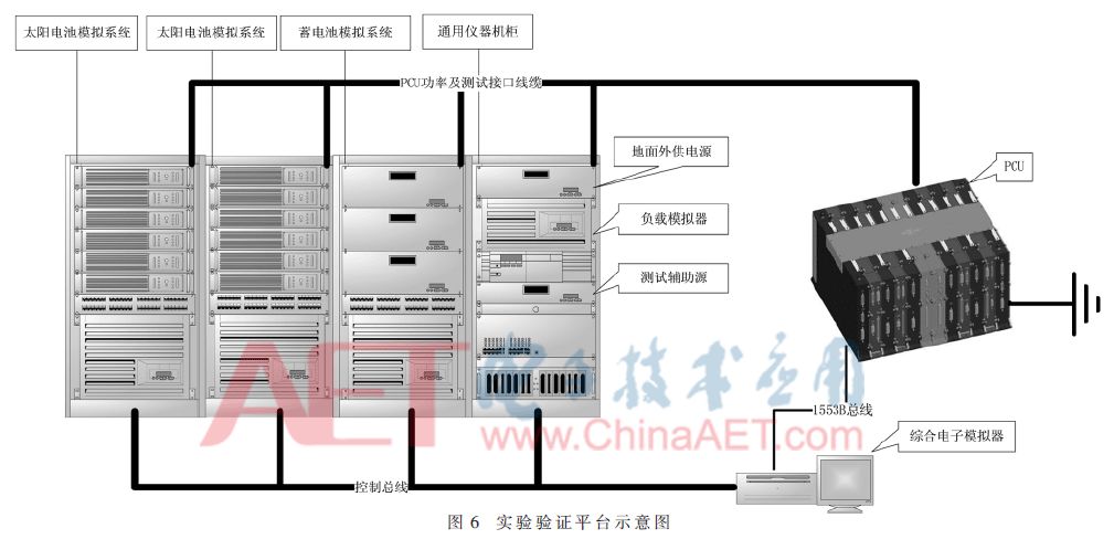
Figure 5 shows the physical diagram of the PCU after adding the BIT module. The PCU can be tested for testability verification using the verification platform shown in Figure 6, which includes a solar array simulator, battery pack simulator, load simulator, comprehensive electronic simulator, auxiliary sources, connecting cables, etc. The comprehensive electronic simulator is an industrial control computer used to simulate telemetry and remote control operations on the PCU.
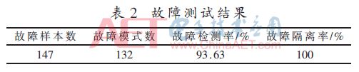
First, determine the fault test sample library, including fault injection methods, criteria for successful fault injection, and success criteria for fault detection and isolation. The selection of the fault sample library adopts a simple random method based on quasi-random sequences to sample from the fault mode library. Then conduct fault injection experiments, injecting one fault from the sample library each time, with the fault injection method selected based on the fault mode for hardware or software injection. By setting the simulator to simulate the satellite’s on-orbit working conditions, fault detection and isolation are performed, and the fault diagnosis results are transmitted to the industrial control computer (also the comprehensive electronic simulator) via the 1553B communication interface. Experimental data is recorded, the product is restored to normal status, and then the next fault is injected until all faults in the sample library are completed. The fault test results are shown in Table 2, from 132 fault modes, 147 times were randomly sampled, generating a fault sample library containing 147 samples. After sequentially conducting experiments on the faults in the sample library, the fault detection rate is calculated to be 93.63%, and the fault isolation rate is 100%. Additionally, experiments show that the BIT system can accurately monitor the performance of the PCU simultaneously.
4 Conclusion
A testability design was conducted on a certain satellite’s PCU, and BIT technology was used to design the BIT hardware and software, achieving on-orbit fault diagnosis and performance monitoring for the PCU, enabling rapid detection and accurate localization of PCU faults, while also allowing real-time monitoring of the PCU’s performance during on-orbit operation, laying a foundation for on-orbit maintenance and health management.
References
[1] Li Bin, Zhang Qiang, Ren Kun, et al. Research on the testability design of spacecraft[J]. Space Control Technology and Application, 2010, 36(5): 13-17.
[2] Xiong Xiaoying, Wang Jiulong, Zhao Yansong. Preliminary study on the testability design methods of manned space products[J]. Manned Spaceflight, 2011(3): 42-47.
[3] Liu Xinjun, Zhang Donglai, Li Anshou, et al. Study on the influence of solar array damage on satellite power system[C]. 10th International Conference on Modelling, Identification and Control (ICMIC), 2018: 1-5.
[4] Wang Xincheng, Sun Hong, Cai Jiren, et al. A safe and controllable SoC testability design[J]. Application of Electronic Technique, 2006, 32(12): 39-41.
[5] Bai Yufeng, Lv Yinpeng. High-efficiency testable design method based on anti-random fault analysis[J]. Application of Electronic Technique, 2017, 43(8): 40-42.
[6] Dong Jiankang, Pan Yue’e, Geng Hong. Design of a fault diagnosis system for an aircraft TCAS electronic system[J]. Application of Electronic Technique, 2011, 37(3): 91-93, 97.
[7] Niu Xingyan, Shen Songhua. Development and solutions of intelligent BIT for aircraft power systems[J]. Journal of Instrumentation and Control, 2006, 27(6) Supplement: 2519-2521, 2553.
Author information:
Liu Xinjun1, Zhang Donglai1, Li Anshou2, Zhu Hongyu2
(1. Harbin Institute of Technology (Shenzhen) School of Mechanical and Electrical Engineering and Automation, Shenzhen, Guangdong 518055; 2. Shenzhen Aerospace Science and Technology Innovation Research Institute, Shenzhen, Guangdong 518057)
