Using FANUC robots as an example!
1 Unable to power on
|
Check and Repair |
Controller Component |
|
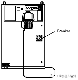
Check 1: The controller circuit breaker is on and has not tripped Repair: Close the circuit breaker |
|
|
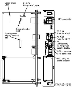
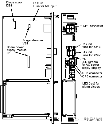
Check 2: Check the LED indicators on the power supply board (PSU) (GREEN) to see if they are lit. Repair: If the LED indicator is off, it may be that the 200V power supply to the PSU is missing or the F1 fuse on the PSU is blown: 1 If the 200V power supply is missing, please check the power supply line 2 If the 200V power supply is provided to the PSU, please cut off the power: A If the F1 fuse is blown, refer to Repair 2 B If the F1 fuse is not blown, please replace the PSU Repair 2: Causes of blown fuses and countermeasures A Check if the CP2 and CP3 connectors between the PSU and other circuit boards have good contact. B If surge absorber VS1 is shorted, please replaceVS1 part number: A50L-2001-0122#G431K C Diode DB1 shorted D Backup power module H1 damaged If B or C has a fault, please replace the corresponding spare parts F1 part number: A60L-0001-0396#8.0A |
|
|
Check and Repair |
Controller Component |
|
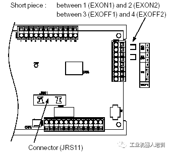
Check 3: Check the signal wiring for EXON1, EXON2, EXOFF1, EXOFF2 on the panel board Repair: If the external power switch function is not used, please short-circuit the signals EXON1 and EXON2, EXOFF1 and EXOFF2; if the external power switch function is used, please check the connecting cable. |
|
|
Check 4: Check if the connection cable of JRS11 on the main board or panel board has good contact. Check 5: Check the top 1, 2, 3 to ensure the 200V power supply on CP1 is connected properly and the machine ON/OFF switch is normal. Please follow these steps to check the PSU: If the LED on the PSU (ALM: red) is lit, please check if the external +24V is grounded or connected to 0V. A If the F4 fuse is blown B Replace the PSU F4 fuse part number: A60L–0001–0046#7.5 |
|
2. Use the LED indicators on the control board to diagnose and troubleshoot
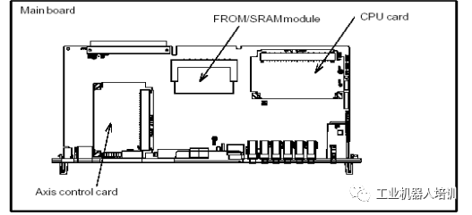
2.1 MAIN BOARD
|
Step |
Repair |
|
1 After powering on, all LEDs are lit |
1 Replace the CPU card *2 Replace the MAIN BOARD |
|
2 When the robot system software starts |
1 Replace the CPU card *2 Replace the MAIN BOARD |
|
3 When the robot system starts, the CPU card DRAM initialization is complete |
1 Replace the CPU card *2 Replace the MAIN BOARD |
|
4 When the robot system starts, DRAM, SRAM initialization is complete |
1 Replace the CPU card *2 Replace the MAIN BOARD *3 Replace the FROM/SRAM card |
|
5 When the robot system starts, the communication IC initialization is complete |
*1 Replace the MAIN BOARD *2 Replace the FROM/SRAM card |
|
6 When the robot system starts, the basic software loading is complete |
*1 Replace the MAIN BOARD *2 Replace the FROM/SRAM card |
|
7 When the robot starts up and loads the basic software |
*1 Replace the MAIN BOARD *2 Replace the FROM/SRAM card |
|
8 When the robot controller communicates with the TP teach pendant |
*1 Replace the MAIN BOARD *2 Replace the FROM/SRAM card |
|
9 When the robot loads option software |
*1 Replace the MAIN BOARD 2 Replace the process I/O board |
|
10 When initializing DI/DO |
*1 Replace the FROM/SRAM card *2 Replace the MAIN BOARD |
When replacing the MAIN BOARD and FROM/SRAM card, the user programs and system settings stored in the machine will be lost. Be sure to back up before replacing the MAIN BOARD and FROM/SRAM card; additionally, backups should also be made before installing the robot system software.
|
Step |
Repair |
|
11 SRAM preparation completed |
1 Replace the axis control card *2 Replace the MAIN BOARD 3 Replace the servo amplifier |
|
12 Axis control card initialization completed |
1 Replace the axis control card *2 Replace the MAIN BOARD 3 Replace the servo amplifier |
|
13 Calibration completed |
1 Replace the axis control card *2 Replace the MAIN BOARD 3 Replace the servo amplifier |
|
14 Robot servo system powered |
*1 Replace the MAIN BOARD |
|
15 During program execution |
*1 Replace the MAIN BOARD 2 Replace the process I/O board |
|
16 During I/O operations |
*1 Replace the MAIN BOARD
|
|
17 Initialization completed |
Initialization ends normally |
|
18 Robot normal |
When the robot is normal, LED1 and LED2 will flash continuously |
When replacing the MAIN BOARD and FROM/SRAM card, the user programs and system settings stored in the machine will be lost. Be sure to back up before replacing the MAIN BOARD and FROM/SRAM card; additionally, backups should also be made before installing the robot system software.
|
7-segment code |
Fault description and countermeasures |
|
|
Fault: RAM parity error on the CPU card Measure 1: Replace the CPU card Measure 2: Replace the MAIN BOARD |
|
|
Fault: RAM parity error on the FROM/SRAM card Measure 1: Replace the FROM/SRAM card Measure 2: Replace the MAIN BOARD |
|
|
Fault: Communication bus error Measure 1: Replace the MAIN BOARD |
|
|
Fault: Error in communication between the controller and the PANEL BOARD Measure 1: Check the communication cable between the MAIN BOARD and the PANEL BOARD. If damaged, replace the communication cable Measure 2: Replace the MAIN BOARD Measure 3: Replace the PANEL BOARD |
|
|
Fault: Servo alarm Measure 1: Replace the servo control card Measure 2: Replace the MAIN BOARD |
|
|
Fault: System emergency stop alarm Measure 1: Replace the servo control card Measure 2: Replace the CPU card Measure 3: Replace the MAIN BOARD |


When replacing the MAIN BOARD and FROM/SRAM card, the user programs and system settings stored in the machine will be lost. Be sure to back up before replacing the MAIN BOARD and FROM/SRAM card; additionally, backups should also be made before installing the robot system software.
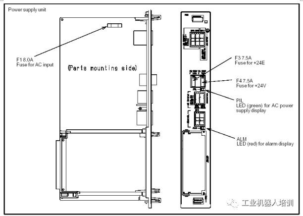
2.2 PSU LED Indicators
|
Fault description and countermeasures |
|
Fault: ALM LED (red) lit indicates PSU alarm Measure 1: Check the F4 (+24V) fuse on the PSU, if blown, replace it Measure 2: Check the +5V, +15V, +24V voltages on the PSU and the related cables and devices connected to it. If damaged, replace them Measure 3: Replace the PSU |
|
Fault: PIL LED (Green) not lit, indicating 200V power supply to the PSU is missing Measure 1: Check the F1 fuse on the PSU, if blown, replace it Measure 2: Replace the PSU |
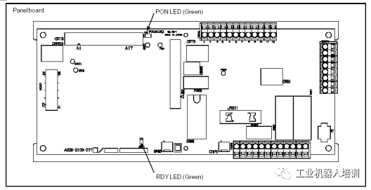
2.3 PANEL BOARD LED Indicators
|
LED |
Fault and Countermeasures |
|
RDY |
Fault: This LED (GREEN) is not lit, indicating a communication interruption between the PANEL BOARD and MAIN BOARD Measure 1: Check the communication cable between the MAIN BOARD and PANEL BOARD, if damaged, replace it Measure 2: Replace the MAIN BOARD Measure 3: Replace the PANEL BOARD |
|
PON |
Fault: This LED is not lit, indicating failure to convert +24V voltage to +5V voltage on the PANEL BOARD Measure 1: Check the CRM63 connector, +24V input power Measure 2: Replace the PANEL BOARD |
2.4 PROCESS I/O Board LED Indicators
|
LED |
Fault and Countermeasures |
|
Process I/O CA/CB/DA
|
Fault: Communication error between the MAIN BOARD and PROCESS I/O board Measure 1: Replace the I/O board Measure 2: Replace the MAIN BOARD Measure 3: Replace the I/O communication cable |
|
Process I/O CA/CB/DA
|
Fault: I/O board fuse blown Measure 1: Replace the fuse Measure 2: Check the peripheral cables Measure 3: Replace the I/O board |
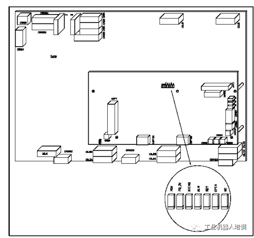
2.5 Servo Amplifier LED Indicators
|
LED |
Color |
Description |
|
P5V |
Green |
Lit: Servo amplifier +5V power supply normal Off: 1; Check the robot RP1 connection cable 2; Replace the servo amplifier |
|
P3.3V |
Green |
Lit: Servo amplifier +3.3V power supply normal Off: Replace the servo amplifier |
|
SVEMG |
Red |
Lit: Robot has emergency stop signal input (if no emergency stop signal input, replace) Off: Robot normal (if there is an emergency stop signal, replace the servo amplifier) |
|
ALM |
Red |
Lit: Servo amplifier fault alarm |
|
RDY |
Green |
Lit: Servo amplifier ready to drive motor Off: If the motor can operate, replace the servo amplifier |
|
OPEN |
Green |
Lit: Communication between the servo amplifier and MAIN BOARD normal Off: 1; Check the communication cable between the servo amplifier and MAIN BOARD 2; Replace the servo control card 3; Replace the servo amplifier |
|
WD |
Red |
Lit: 1; Replace the servo amplifier 2; Replace the servo control card 3; Replace the CPU card 4; Replace the MAIN BOARD |
|
D7 |
Red |
Lit: 1; Check the internal cables of the controller 2; Replace the emergency stop board 3; Replace the servo amplifier |
If the industrial robot has a problem, don’t be afraid, contact us
Manager Yang 18624044906