2016 Microcomputer and Applications Issue 3 Author: Yuan Qianqian
Abstract: This article provides a detailed study of the computer boot process and system loading, combining the collaborative calling mechanism between hardware and software. It offers a relatively comprehensive discussion of the entire process from pressing the power button to loading the operating system, ultimately displaying the boot interface. This is very helpful for beginners to gain a comprehensive understanding of the boot process.
0 Introduction
For most people outside of computer-related majors, their understanding of computers is limited to basic operations, and they do not have a deep understanding of the internal operating principles. Exploring the boot process can help them gain a deeper understanding of computers. The computer goes through a series of very complex processes from powering on to displaying the operating interface. First, the computer must detect and configure all critical hardware devices in a certain order, then load the operating system from the storage device according to the boot sector, and further complete the system initialization work. Understanding the computer boot process helps users strengthen their daily maintenance of computers and improve boot speed by upgrading hardware performance, giving those interested in exploring computer science a preliminary understanding of computer operating mechanisms.
1 Power-On Self-Test
The initialization boot process of a computer is called bootstrapping, also known as “Boot”. The term originates from a contradiction that existed when the concept of computer booting was first established: a computer must first start a program for the machine to run, but the computer cannot run if it is not started. How to start the computer was once a puzzling question. After a long period of time, engineers eventually overcame this contradiction by writing the boot program into memory, linking the computer self-check with the operating system loading, thus enabling the computer to start and run normally.
1.1 CPU Preparation
When the power button is pressed, the power supply begins to provide power to the motherboard and other devices. Due to unstable voltage at the beginning, the control chipset on the motherboard sends and maintains a positive pulse signal greater than 2 ms, known as the RESET signal, to the CPU. Generally, after 100 to 500 ms, the power supply generates a stable logic signal, and when the chipset detects this signal, it withdraws the RESET signal. The computer’s Central Processing Unit (CPU) begins reading instructions from address FFFF-0000H, at which point the Basic Input and Output System (BIOS) finds its actual boot code thread based on the jump instruction stored here, initiating a series of checks and configurations.
1.2 Basic Functions of System BIOS
BIOS plays an important role in the computer system as it is the low-level code that interacts directly with hardware. It stores the most important basic input/output program, power-on self-test program, and system auto-start program. It is powered by a special battery on the computer motherboard, reading and writing specific information about system settings from Complementary Metal Oxide Semiconductor (CMOS) to provide the basic functions of controlling hardware devices for the operating system. BIOS includes system BIOS (i.e., motherboard BIOS), graphics card BIOS, and other devices (such as integrated drive electronic controllers, small computer system interface cards, or network cards) BIOS. BIOS is generally stored in Read Only Memory (ROM), which can permanently retain data and program information even if the machine is powered off.
1.3 BIOS Detection Process
The boot code of system BIOS first performs a Power-On Self-Test (POST), mainly checking whether some key devices in the system exist and function properly, such as memory and graphics cards. Since the graphics card is not yet initialized at this time, if there is a hardware problem detected during self-check, the system will emit a beep, with the length and number of beeps representing different error types. If no errors occur, the POST process will end quickly, and then other codes will be called for a more complete hardware detection.
Next, the system BIOS will search for the graphics card BIOS (located at address C0000H), and upon finding it, will call its initialization code to initialize the graphics card. For most graphics cards, some initialization information will be displayed on the screen, such as manufacturer and model, but it will almost flash by. The system BIOS will then look for the BIOS programs of other devices, calling their initialization codes to initialize the relevant devices. Finally, the system BIOS will display its own boot screen, listing the type, serial number, and version number of the system BIOS.
Next, the system BIOS will detect and display the type and operating rate of the CPU, then test all Random Access Memory (RAM), while displaying the memory test progress on the screen. After the memory test passes, the system BIOS will start detecting standard hardware devices installed in the system, including hard disks, CD-ROMs, etc. Next, it will detect and configure the Plug and Play devices installed in the system, displaying the names and model information of the detected devices and allocating available resources for them.
After all hardware devices have been detected, the screen will display various resources and related working parameters used by standard hardware devices. The system BIOS will then update the Extended System Configuration Data (ESCD), which is used by the system BIOS to exchange hardware configuration information with the operating system. This data is stored in CMOS and is usually only updated when the system hardware configuration changes.
2 Master Boot Record
After the hardware self-check is complete, the operation interface of the system BIOS will display the user-specified boot device order, which can include floppy disks, hard disks, or CDs. The devices listed first have priority in transferring control. The BIOS reads the Master Boot Record (MBR) from the boot order specified device and places it in memory address 7C0000H, searching for the information to be read next from the MBR.
2.1 Structure of the Master Boot Record
The Master Boot Record is located on the first sector of the zero cylinder and zero head of the hard disk, totaling 512 B. If the last two bytes of these 512 B are 55AAH, it indicates that this device is bootable; if not, it indicates that the device cannot boot, and control needs to be transferred to the next device in the boot order list. The byte code meanings of the standard MBR are shown in Table 1.
2.2 Partition Table
After finding the Master Boot Record, the system begins to read the valid partition table. The partition table is 64 B in length, subdivided into four primary partitions, each occupying 16 B. There are many benefits to partitioning a hard disk, as different operating systems can be installed in different partitions, allowing for multi-system coexistence. The Master Boot Record determines whether the primary partition is active by checking the first byte of the partition table, with only one of the four primary partitions being active. The partition table structure is shown in Table 2.
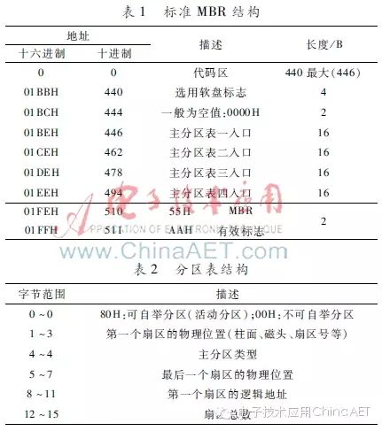
From Table 2, it can be seen that the number of sectors in the primary partition occupies 4 B, so the maximum total number of sectors for a primary partition is 232. If each sector size is 512 B, then the maximum for each partition is 2 TB (1 TB = 240 B). The logical address of the sector also occupies 32 bits, so the maximum usable space of the hard disk is 2 TB. Therefore, if one wants to expand the hard disk space, there are two methods: one is to increase the number of bytes per sector, and the other is to increase the total number of sectors. Currently, the storage capacity of hard disks has reached 3 TB, and related technology continues to develop, so storage capacity will still increase..
3 Hard Disk Booting
3.1 Booting the Hard Disk Through the Primary Partition
The computer reads the Volume Boot Record (VBR) of the first sector of the active partition, also known as the partition boot sector, by locating the corresponding VBR through the starting address of the primary partition’s logical address. If the storage device has not been partitioned, such as a floppy disk, then the VBR is located in the first sector of that device. The VBR contains a lot of information, such as the byte size of each sector, the number of sectors contained in each cluster, the size of the reserved sector, the number of files in the File Allocation Table (FAT), the size of each FAT in sectors, and the location of the cluster storing root information, etc. Through the VBR, the system BIOS can find the specific location of the operating system within this partition, and then the computer will begin to search for the address information to load the operating system. Figure 1 shows the entire logical structure of the hard disk.
3.2 Booting the Hard Disk Through the Extended Partition
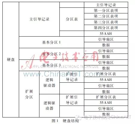
Among the four primary partition tables, only one can be defined as an Extended Partition (EP), which can contain multiple logical partitions. The computer first reads the first sector of the extended partition, which is the “Extended Boot Record” (EBR), and the EBR contains a 64 B partition table. The extended partition can contain countless logical partitions. However, computers rarely choose this method to boot the operating system. If the operating system is installed in the extended partition, it generally chooses to boot the operating system through a boot manager.
3.3 Booting the Hard Disk Through the Boot Manager
In this case, the computer does not transfer control to a specific partition when reading the MBR, but runs a pre-installed boot manager, allowing the user to choose which operating system to boot. In Linux systems, the boot manager (Grand Unified Bootloader, Grub) uses the first 446 B of the MBR as its starting execution program, allowing the selection of different kernels on the operating system partition and passing boot parameters to these kernels.
3.4 File System
In an operating system, the subsystem related to files and directories is called the file system, which is used to organize and manage files. It organizes the storage space into physical locations and provides a mechanism for indexing the data stored within. It also establishes a hierarchical indexing relationship, converting the physical partitions of the disk into logical partitions, and allocating data to the positions of the logical partitions. Common file systems used in Microsoft systems include FAT16, FAT32, and NTFS (New Technology File System).
FAT16, which is a 16-bit file allocation table, is the most widely used. In operating systems like Microsoft, disk file allocation is done in units of “clusters”. Regardless of the proportion of the file that occupies the entire capacity, each cluster corresponds to only one file, and it can only support a maximum partition size of 2 GB, which results in low actual space utilization of the hard disk. With the improvement of computer hardware performance, Microsoft introduced the enhanced file system FAT32, which can support a maximum disk size of 2 TB and uses smaller clusters to more effectively store information. The FAT32 file system can relocate the root directory and use backup copies of the FAT, in addition, its boot record is included in a structure containing critical data, reducing the possibility of system crashes. NTFS was developed alongside Microsoft’s NT operating system, offering advantages in security and stability, making it less prone to file fragmentation. NTFS can support file sizes up to 64 GB, far exceeding the 4 GB limit under FAT32, and it can support long file names.
4 Loading the Operating System
Once the operating system is determined, its kernel is first loaded into memory for system initialization and loading device drivers. In Linux systems, the operating system kernel located in the /boot directory is loaded first. The kernel is the core part of the operating system, with main functions including controlling and managing event scheduling and synchronization, inter-process messaging, memory management, and process management. After the kernel is successfully loaded, the disk file system is mounted, and the program in /sbin/init is executed based on the configuration file, generating the init process. This is the first process after Linux starts, setting the process control block’s process identification number (PID) to 1, with all other processes created subsequently as its child processes. Then, the init thread begins loading various system modules, such as window programs and network programs, and finally executes the /bin/login program, presenting the login interface where users enter their username and password. After successfully logging in, the system boot process is completed smoothly, and users can proceed with normal daily use.
5 Conclusion
The computer boot process involves knowledge of the underlying hardware and system software. After understanding the entire process, users can enhance their understanding and maintenance of computer systems. If problems occur during the computer boot process, users can analyze the issues based on different stages of the problem and find solutions to successfully run the computer.