1.1 Introduction In January of this year, GigaDevice launched the GD32F190 series microcontrollers in Beijing. The new microcontroller is based on the Cortex-M3 core, and its 5V wide voltage design makes it more suitable for industrial applications. As the latest member of the GD32 family, the GD32F190 series continues the core value of combining higher performance with better pricing found in GD32 value MCUs. The products in this series will officially enter mass production this month. Previously, we conducted an in-depth review of the development board for the concurrently released F170 series, and today we will introduce the GD32F190R-EVAL development board.1.2 First Impressions
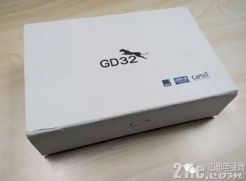
Those who have used GD32 official development boards know that the packaging is generally as shown in the image above, a beautiful white box with a standard GD32 logo and a cheetah graphic on the front, indicating that GD32 aims to be the best in the 32-bit market.
The logo of the ARM-Cortex core is located in the lower right corner of the front. The side features the company logo. The simple packaging gives a high-end feel.
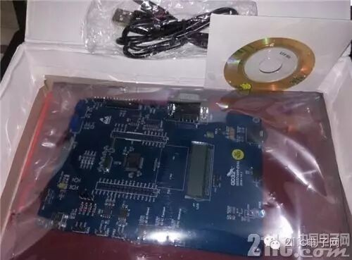
Opening the package reveals the development board, a CD with development materials, and a data cable. The box uses two layers of foam for shock protection. At first glance, the development board appears to be well-made, with all modules arranged neatly. It is clear what resources the development board provides; due to its spacious design, it does not look crowded, but rather gives a sense of wasted space.
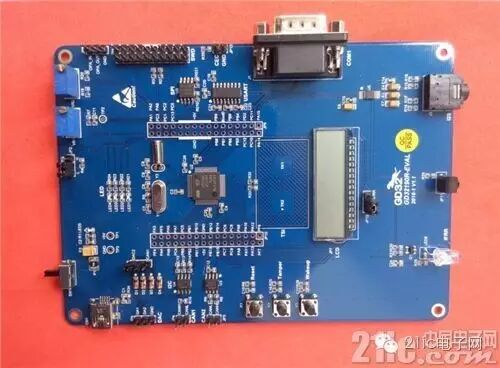 Development board front
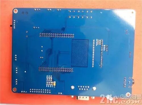 Development board back
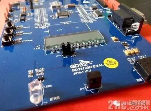 Development board model label
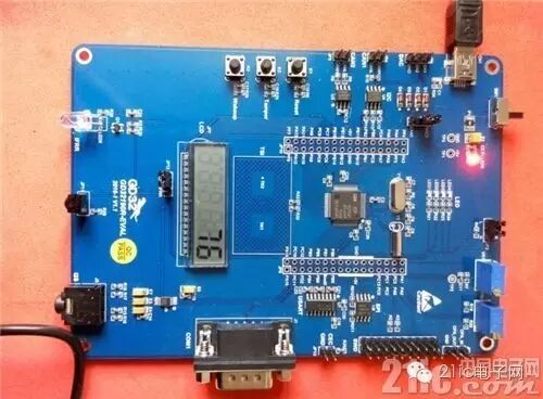
From the above images, we can see that almost all components of the development board are concentrated on the front. The development board provides a segment LCD, a 9-pin serial port interface, a mini-USB interface, and some other components. The board adopts a blue background with white printing style.
Comparison with STM32-F030-discoveryWe see that the GD32F190R-EVAL is significantly larger than the STM32F030 discovery board. We note that the GD32F190R-EVAL does not provide an onboard programming tool, while the small STM32 board does provide a programmer. However, from the appearance, it is clear that the GD32 offers richer onboard peripherals, such as an LCD screen, a 3.5mm audio output interface, an infrared interface, and one chip each for SPI, I2S, and I2C interfaces.1.3 Onboard Resources
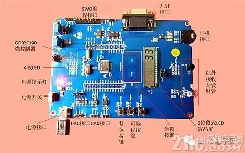 Onboard resource configuration image
Additionally, we have created a block diagram of the resources for everyone to view.
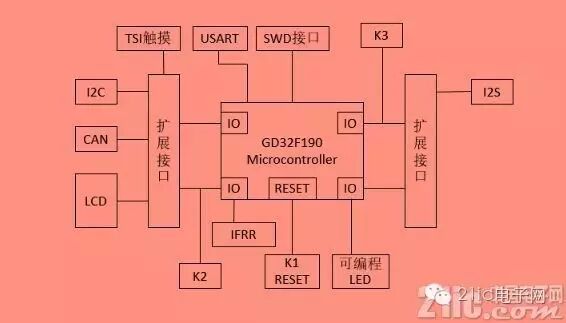 Resource block diagram
From the application board of this development kit, we can clearly see that it includes the following resources: core board area and expansion interfaces, 3 buttons and 2 touch buttons, an I2C interface AT24C02C-SSHM-T, an I2S interface CS434, and one 3.5mm audio output interface, an SPI interface GD25Q40, a light sensor (infrared interface), 4 programmable LEDs, an LCD segment display, a serial port chip MAX3232, and a CAN interface chip TJA1050T.
We note that the development board provides one mini-USB interface, but this interface is only for USB power supply and does not provide data communication, as shown in the image below.
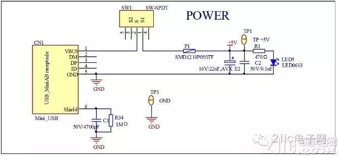 Power supply
LEDs are also driven directly, using a series current-limiting resistor, with a common cathode grounding, as shown in the image below.
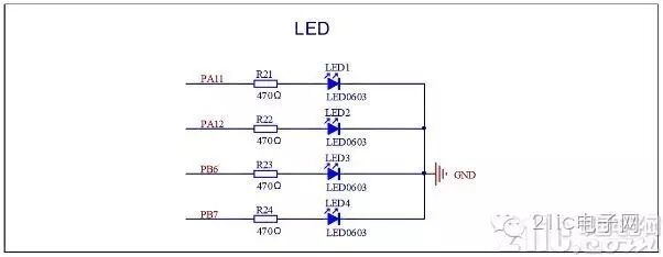 LED wiring diagram
The serial port circuit also uses a common implementation method from the 51 microcontroller era. Those who have worked with 51 microcontrollers will be familiar with the following serial level conversion circuit, which uses a 9-pin male connector.
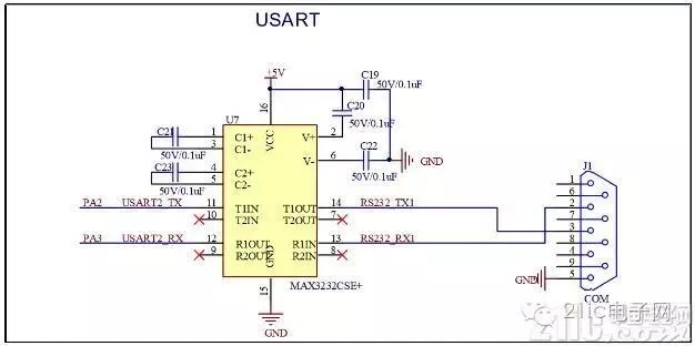 Serial level conversion circuit
To facilitate learning ADC conversion, the development board provides a variable resistor and related circuits, which can be of reference value for those who do not know how to handle ADC output circuit design, as shown in the image below.
 Analog-to-digital conversion input circuit
The SPI interface connects to an I2S interface stereo DAC audio chip CS4344, with a resolution of 24 bits. The reference circuit provided by this development board is shown in the image below.
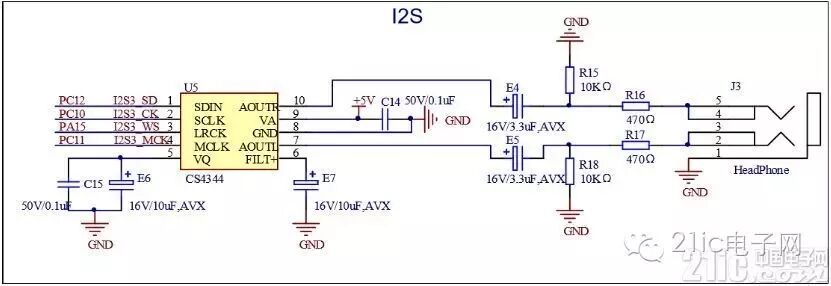 I2S interface circuit
Other circuits can be found in the development board circuit schematic.1.4 Driver Installation
Since the GD32F190R-EVAL does not provide an onboard programming tool, there is no need for driver installation. However, if you use a USB-RS232 converter, you will need a secure driver. Currently, for Windows 7 and above versions, the driver can be automatically installed via the internet. I am using Windows 10, and after the automatic secure driver installation, the device manager shows the following port.
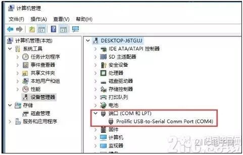 Serial port adapter driver
1.5 DEMO Testing
 Development board power-on test
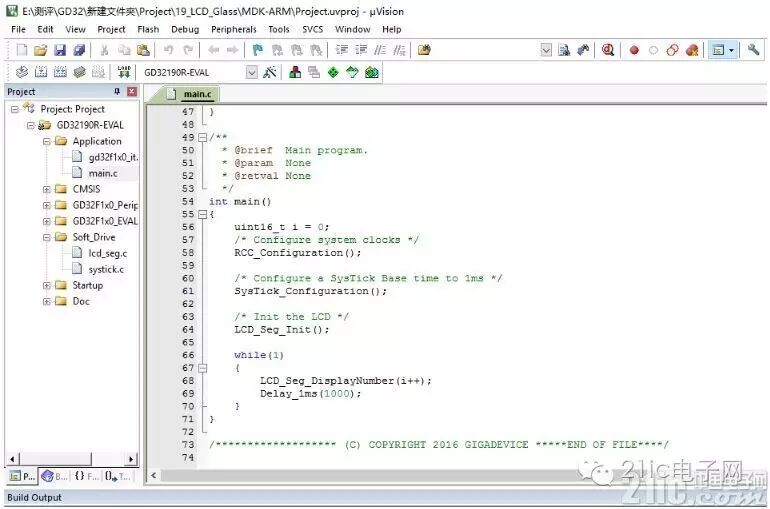
By connecting the development board to the computer via USB, we found that the LCD screen starts counting seconds. Pressing the three buttons, only the reset button responds, indicating that the demo program on this development board is simply a second-counting program displayed on the LCD screen. We checked the provided example and found the demo code.
 DEMO example code
From the code above, we can see that it is indeed simple, only counting seconds, and it uses a delay function to achieve a 1-second timer. We see that the LCD screen can display a maximum of 6 digits. The development materials CD provides a total of 20 examples, which include learning about all the onboard external devices carried by the development board, and the demo carried by the development board is the 19th example in the list.
1.6 Development Environment and Programming
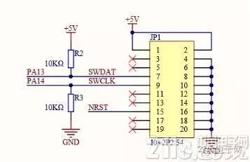
As mentioned earlier, this development board does not provide a programming tool, only a SWD programming interface, which is a 10×2 pin header interface. The port distribution is shown in the image below, and in fact, only 5 effective interfaces are available: SWDAT, SWCLK, NRST, GND, VCC.
SWD programming interface
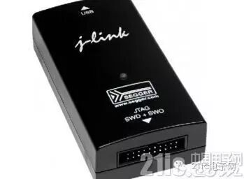 J-LINK Emulator
The evaluation board uses a Mini USB to provide 5V power. To download programs to the evaluation board, a set of J-Link tools is required. After selecting the correct startup method and powering on, LED5 will light up, indicating that the evaluation board is powered normally. Therefore, if you want to use this development board, you will need to prepare a J-LINK yourself. I used the STM32’s ST-LINK for testing, but it could not read the chip, likely because ST-LINK is not suitable for this development board. As shown in the image above, J-LINK has a 20-pin interface, which is also why the development board provides a 20-pin interface. Additionally, the retail price of J-LINK is around 100 yuan, which may be one reason why this development board does not provide a programmer.
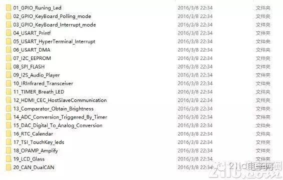
In terms of program development, in addition to providing examples for testing the onboard peripherals of the development board, examples for each usage method of the internal and external peripherals are also provided, as shown in the image below.
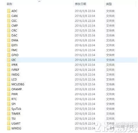
On-chip peripheral example directory
Of course, these are all based on the firmware library. GD32 provides a rich and easy-to-use firmware library to help developers get started quickly. We will attach the download link for all files on the material CD later.
The official programming software comes in two versions: GD-Link Programmer and GD32 MCU ISP Programmer. According to my tests, ISP does not support programming this development board, and the manual does not mention that this method can be used for programming. After testing, GD-Link Programmer cannot run on Windows 10 due to version compatibility issues, but it can run on XP systems. It is recommended that the official team recompile the source code to be compatible with the latest operating systems, preferably using QT development, as currently only QT environment development can well support the entire series of Windows systems.
For the integrated development environment, the official recommendations are IAR for ARM and MDK Keil for ARM. This can be seen from the provided example project, as shown in the image below.
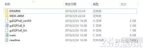 Example project file structure
1.7 Summary
The GigaDevice GD32F170/190 series is a new 32-bit 5V wide voltage value MCU based on a 72MHz Cortex-M3 core, continuously providing high cost-performance solutions for industrial and home appliance applications with high noise resistance, high reliability, high integration, and high efficiency advantages. The GD32F170/190 series products adopt a new process design that can operate in a wide voltage application environment of 2.5V-5.5V and can easily connect to 5V systems without additional voltage converters, with I/O ports capable of withstanding 5V levels. It supports advanced power management and has three power-saving modes. In battery-powered situations, the built-in high-precision calibrated real-time clock (RTC) has a standby current of less than 1uA. The GD32F170 and GD32F190 series products have a maximum core clock frequency of 72MHz and are equipped with 16KB to 64KB of built-in Flash and 4KB to 8KB of SRAM, with zero-wait access to Flash memory, achieving a performance of up to 74 DMIPS at the maximum main frequency, and a 20% improvement in code execution efficiency compared to similar Cortex-M3 products on the market, and a 35% improvement compared to Cortex-M0+ products.
The 5V wide voltage value MCU integrates a wealth of innovative peripheral resources. It supports three-phase PWM complementary output and Hall sensing interfaces with a 16-bit advanced timer for vector control, and has up to 10 16-bit general-purpose timers, 1 32-bit general-purpose timer, 2 16-bit basic timers, and 1 multi-channel DMA controller. Peripheral interface resources include 2 USARTs, 3 SPIs, 3 fast I2Cs, and 2 I2S. Among them, the SPI interface can work at a maximum frequency of 30MHz and supports 4-wire synchronous serial mode, making it easy to connect to external large-capacity NOR Flash for fast access. The fast I2C interface is the first to be compatible with the technical specifications of the resident ID verification security control module interface, making it fully suitable for localized industry custom applications. Additionally, for home multimedia devices, it is equipped with hardware circuits for consumer electronics control (CEC) bus supporting HDMI interfaces, and for touch applications such as buttons and slides, it integrates a touch sensing interface (TSI). The built-in LCD controller also supports connecting to super-twisted nematic (STN) image display panels, capable of directly driving 256 (8×32) segment codes for high-quality, high-contrast LCD displays. Up to 80% of the available GPIOs have multiple selectable functions and support port remapping, providing excellent flexibility and ease of use to meet various application needs.
As a leading 5V MCU product in the industry, the GD32F170/190 chips also possess excellent anti-interference performance and electrostatic protection levels. The strong system electromagnetic noise immunity is particularly suitable for control applications in electrically harsh environments, with chip-level ESD protection levels reaching 7KV in human discharge mode and 1KV in device discharge mode, far exceeding industry safety standards and reducing the need for external circuit protection components. Additionally, GigaDevice provides hardware fault tolerance design, self-check programs, and software testing libraries to help users meet the requirements for IEC 60730 Class B appliance safety certification, thus developing more durable and reliable products.
However, there seem to be many shortcomings with this development board, making it unsuitable for beginners. Firstly, the USB interface only provides power supply functionality, while serial communication uses a 9-pin interface, which also consumes a level conversion chip. Why not directly provide USB-to-serial functionality through the USB interface? This would save a 9-pin interface and make it easier for laptop users. Based on my experience, desktop computers have gradually phased out traditional 9-pin serial ports in recent years, so the circuit design for serial communication is somewhat outdated; using a USB interface would be better. Another failure in the development board design is that it does not provide programming tools. As a beginner, one should be able to practice immediately with a development board, but this board does not provide a programmer, requiring users to purchase a J-LINK emulator separately, increasing the learning cost.
Although the core chip functionality is powerful, the provided development board does not allow users to feel convenience, which may lead development board users to intentionally avoid it during the selection phase, thus significantly impacting subsequent chip sales and promotion. I hope these two aspects will be upgraded in the next version.
1.8 Related Material DownloadsOfficial material download address: http://gd32mcu.21ic.com/ Development board material CD file download address: http://pan.baidu.com/s/1nu2lN9B Click to read the original text for more detailsHighly Recommended

Comprehensive Analysis of Switching Power Supplies: Everything You Want to Know is Here

After reviewing these 100 knowledge points, analog electronics is actually not that difficult

It turns out that wristbands and step counting on WeChat are played this way…
