Project Overview
The ESP32 Oscilloscope is an oscilloscope project based on the ESP32 microcontroller, featuring an intuitive web interface that displays the captured signals. This project was initially designed to showcase the multitasking capabilities of the ESP32, but it has now evolved into a self-contained oscilloscope solution.
This oscilloscope can display up to 736 samples on the screen. However, the sampling rate may not always be stable, as the ESP32 also needs to handle other tasks. This means that in different usage scenarios, the ESP32 may not consistently maintain the ideal sampling frequency.
How the Oscilloscope Works
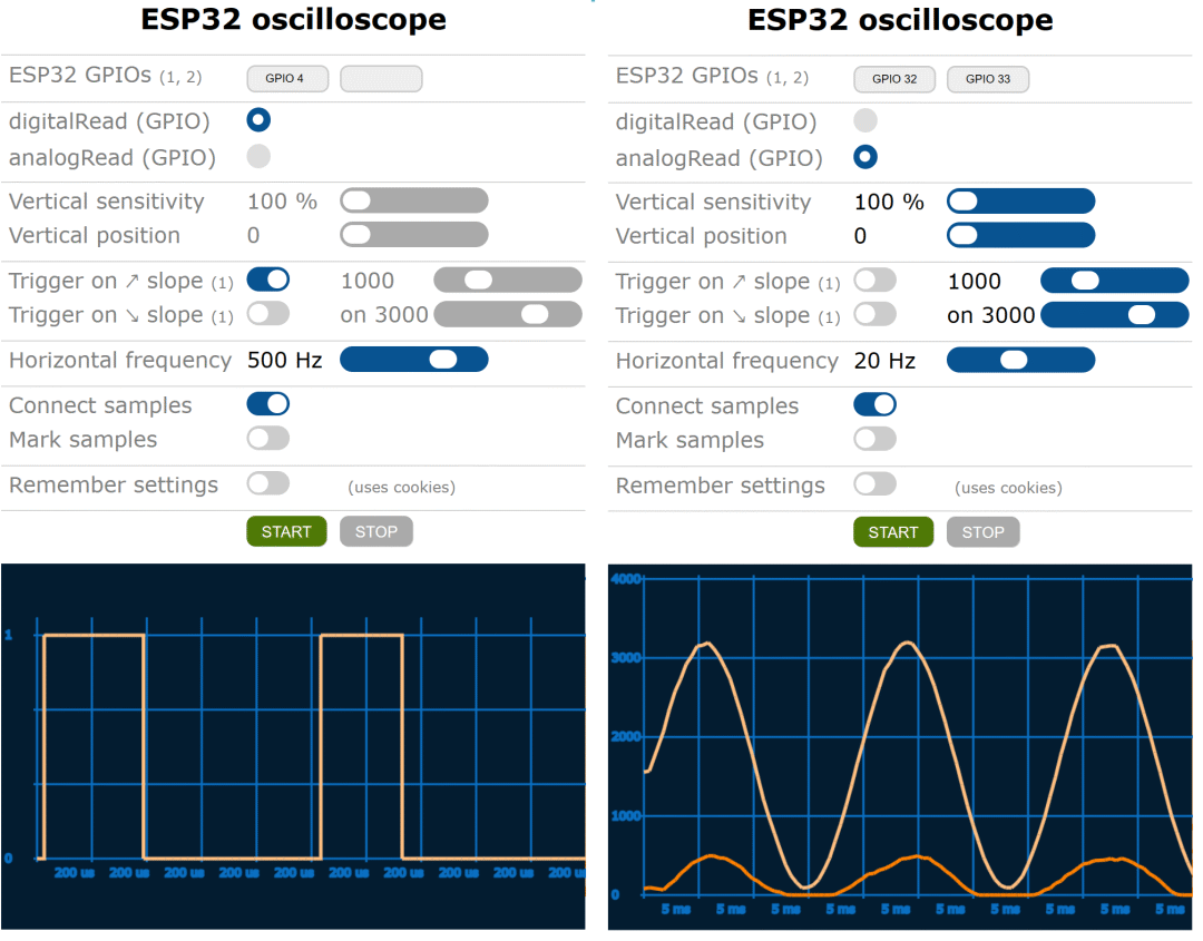
The ESP32 Oscilloscope allows users to visualize the actual waveforms by processing and displaying digital or analog signals obtained from the input pins. The digital values of the input signals range from 0 to 1, while the analog values range from 0 to 4095, representing a voltage range from 0V to 3.3V.
Users can adapt the project to their needs by modifying the <span>oscilloscope.html</span> file, such as specifying which GPIOs to use as digital inputs and which as analog inputs, allowing for more effective signal monitoring.
Setup Instructions
To start the ESP32 Oscilloscope project, users need to follow these setup steps:
-
1. Copy all files from this project into the
<span>Esp32_oscilloscope</span>directory. -
2. Open the
<span>Esp32_oscilloscope.ino</span>file using the Arduino IDE. -
3. In the
<span>Esp32_servers_config.h</span>file, replace<span>YOUR-STA-SSID</span>and<span>YOUR-STA-PASSWORD</span>with your own WiFi SSID and password. -
4. Select a SPIFFS partition scheme (choose “Partition Scheme” from the “Tools” menu).
-
5. If your ESP32 board does not have flash memory, comment out the
<span>#define FILE_SYSTEM FILE_SYSTEM_LITTLEFS</span>line, so the oscilloscope will use program memory instead of the file system to store the<span>oscilloscope.html</span>file. -
6. Compile and run the sketch for the first time; the ESP32’s flash memory will be formatted, note that this will erase all information in the flash memory.
-
7. Use FTP to upload the relevant images and HTML files to the ESP32’s /var/www/html directory.
-
8. Open
<span>http://YOUR-ESP32-IP/oscilloscope.html</span>in a browser to access the oscilloscope interface.
Handling Inverted Signals
On some ESP32 boards, you may encounter issues with inverted analog signals. This can be resolved by commenting or uncommenting the <span>INVERT_ADC1_GET_RAW</span> and/or <span>INVERT_I2S_READ</span> compilation directives in <span>oscilloscope.h</span>. If your ESP32 board supports the I2S interface (such as the ESP32 DevKitC or NodeMCU-32S), you can also choose whether to use this interface. Using the I2S interface can improve the sampling frequency and quality of individual analog signals, but the downside is that multiple analog oscilloscopes cannot be used simultaneously.
Notes on Analog Readings
The ESP32 has two Successive Approximation Registers (SAR), but only ADC1 can be used for analog readings in the oscilloscope. The GPIO pins for ADC1 include 36, 37, 38, 39, 32, 33, 34, and 35. The ADC2 pins (GPIO4, 0, 2, 15, 13, 12, 14, 27, 25, 26) can only be used for analog readings when WiFi is not operational, so these ADC2 pins are unavailable when using the ESP32 Oscilloscope.
Conclusion
The ESP32 Oscilloscope provides users with a simple and efficient way to monitor signals in real-time. Through the web interface, users can easily access the oscilloscope and customize settings according to their needs. Whether for hobbyists or professional engineers, this ESP32 oscilloscope can play an important role in daily work, experiments, and learning.
Project URL: https://github.com/BojanJurca/Esp32_oscilloscope