01
Introduction
This 5-channel line tracking sensor integrates 5 pairs of gray sensors, using TTL communication mode, and supports both digital and analog signal outputs, providing higher anti-interference capability compared to infrared line tracking sensors.
02
Principle
The gray sensor consists of a high-brightness white light emitter and a light-sensitive receiver. The emitter emits concentrated bright white light, which is reflected by different environmental backgrounds and received by the light-sensitive receiver. The impedance of the light-sensitive receiver changes with the intensity of the reflected light; the stronger the reflected light, the lower the resistance. Finally, through voltage division and operational amplifier comparison circuits, dual output of digital and analog signals is achieved.
What are the differences between gray sensors and infrared sensors?
- Light Source: The gray sensor uses white visible light as its light source, while the infrared sensor uses infrared light, which is invisible with a wavelength of 850-940nm.
- Detection: The gray sensor relies on the color depth or material reflectivity differences of the object’s surface; for example, the greater the reflectivity difference between a black line and a white background, the more sensitive the detection. The infrared sensor has a built-in infrared filter to eliminate interference from visible light in strong light environments.
- Applications: The gray sensor can be used for complex PID line tracking control, while the infrared sensor is suitable for simple line tracking projects in beginner robot competitions.
03
Usage Instructions
- Communication Method: IIC
- Operating Voltage: 3~5V
- Interface Type: PH2.0-4Pin (G V SDA SCL)
- Detection Height: 0.5cm ~ 4 cm, it is recommended that the probe be about 1CM from the ground for optimal performance.
- Output Values:
- Analog Value: When detecting a black line or approaching a black line, the value increases; generally, a value greater than 800 indicates black under normal conditions.
- Digital Value: Outputs 0 when a black line is detected, and outputs 1 when no black line is detected.
- High Threshold: Default is 800; when the analog value increases and exceeds this high threshold, the digital value will change to 0.
- Low Threshold: Default is 500; when the analog value decreases and falls below this low threshold, the digital value will change to 1.
How to set appropriate high and low thresholds?
- Install the line tracking sensor on the vehicle, with the probe approximately 1cm above the ground.
- Place the vehicle on the ground so that all probes can detect the black line, read the sensor’s analog value, and record it as x.
- Place the vehicle on the ground so that all probes cannot detect the black line, read the sensor’s analog value, and record it as y.
- Set the high threshold to: (X – Y) * 2 / 3 + Y
- Set the low threshold to: (X – Y) / 3 + Y
04
Wiring
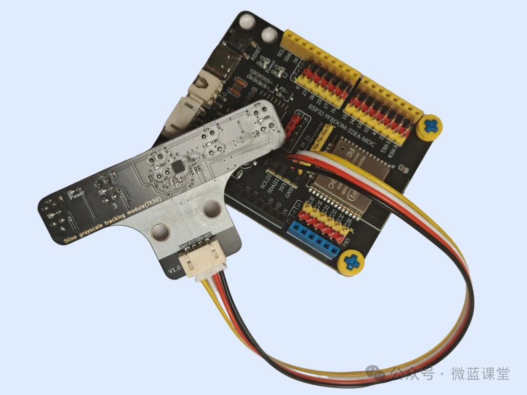
05
Program
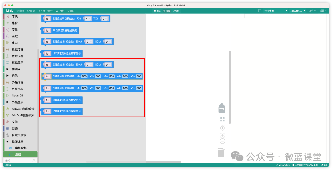
06
Demonstration
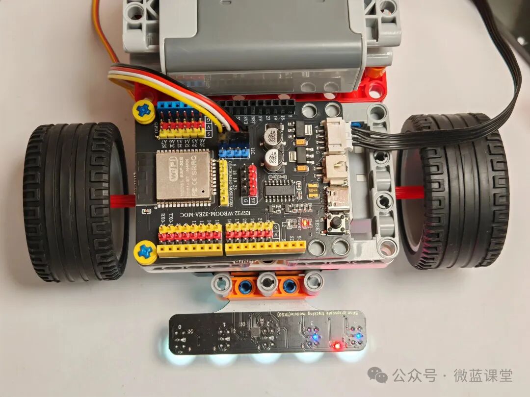
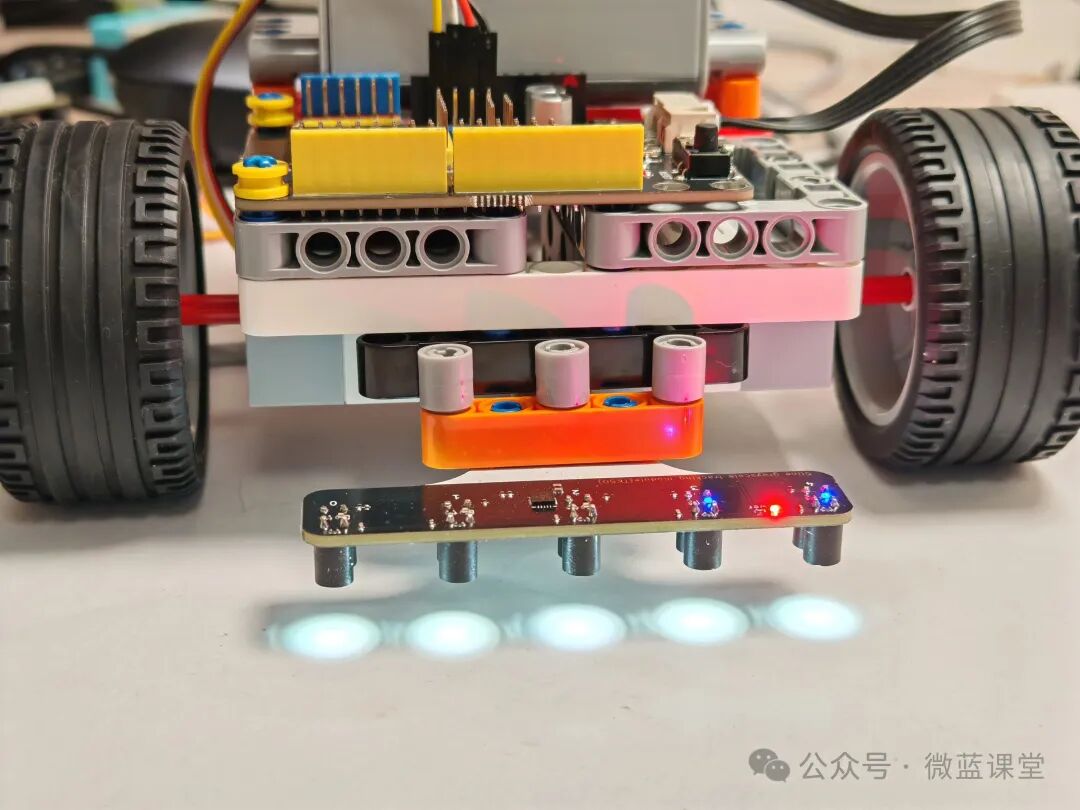
Students who need accessories can purchase them from my Taobao store under my name.
 Follow me for more shares|Weilan Classroom