EFR32 (Simplicity Studio) Development Environment and Practical Notes 📝
Introduction: Overview of the EFR32 Series Wireless SoCs
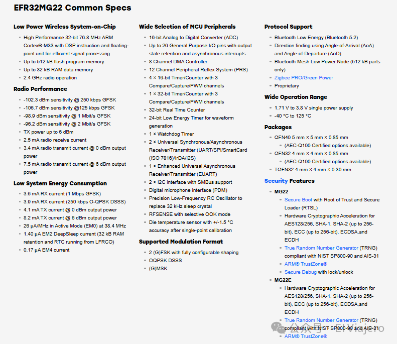
The EFR32 series of wireless System-on-Chips (SoCs) from Silicon Labs is designed as the core processing unit for modern Internet of Things (IoT) applications. The key features of these SoCs include their high performance, low power consumption, and robust multi-protocol wireless connectivity capabilities. The EFR32 series typically integrates a powerful ARM Cortex-M series microcontroller core (such as Cortex-M33 or Cortex-M4) and is equipped with a rich set of on-chip peripherals, including various communication interfaces (USART, I2C, SPI), analog components (ADC, DAC), and diverse timers and pulse width modulation (PWM) channels. Its outstanding wireless performance supports multiple standards, including Bluetooth Low Energy (BLE), Bluetooth Mesh, Zigbee, Thread, Wi-SUN, and proprietary wireless protocols, with some models even supporting concurrent multi-protocol operation. Additionally, the EFR32 series places a strong emphasis on energy efficiency, offering various low-power modes and fast wake-up mechanisms, making it highly suitable for battery-powered IoT devices. In response to the growing security demands of IoT, the newer EFR32 series also integrates advanced hardware security features, such as Secure Vault™ technology, providing secure boot, encryption acceleration, true random number generation, and secure debugging capabilities. It is precisely due to the highly integrated, multifunctional, multi-protocol nature of the EFR32 SoCs, along with their extreme focus on low power and security, that a similarly powerful and efficient integrated development environment is required, which is the necessity of Simplicity Studio — designed to simplify the configuration and application development of such complex systems.
1. Overview of Simplicity Studio IDE and Development Approach
The primary integrated development environment provided by Silicon Labs (Silabs) for its EFR32 series wireless SoCs is Simplicity Studio. This is a multifunctional platform based on Eclipse, with its core design philosophy centered around high integration, component management, and configuration-driven development. The goal is to simplify the increasingly complex development of Internet of Things (IoT) applications, enabling developers to quickly build and configure projects using graphical tools while maintaining control over the underlying hardware.
Unlike some traditional embedded development processes, Simplicity Studio emphasizes driving the entire project build with a centralized project configuration file (usually a <span>.slcp</span> file). This file records key information such as the SDK version the project depends on, the target chip, installed software components, pin assignments, and peripheral parameter configurations. When developers modify these configurations through the graphical interface and save them, the IDE automatically generates or updates the relevant underlying configuration files and initialization code, allowing developers to write application logic based on these automatically generated foundations.
Main Features:
- Software Components: Provides a large number of pre-built drivers, protocol stack modules, services, and third-party libraries that developers can “install” into their projects as needed. The IDE manages the dependencies between components.
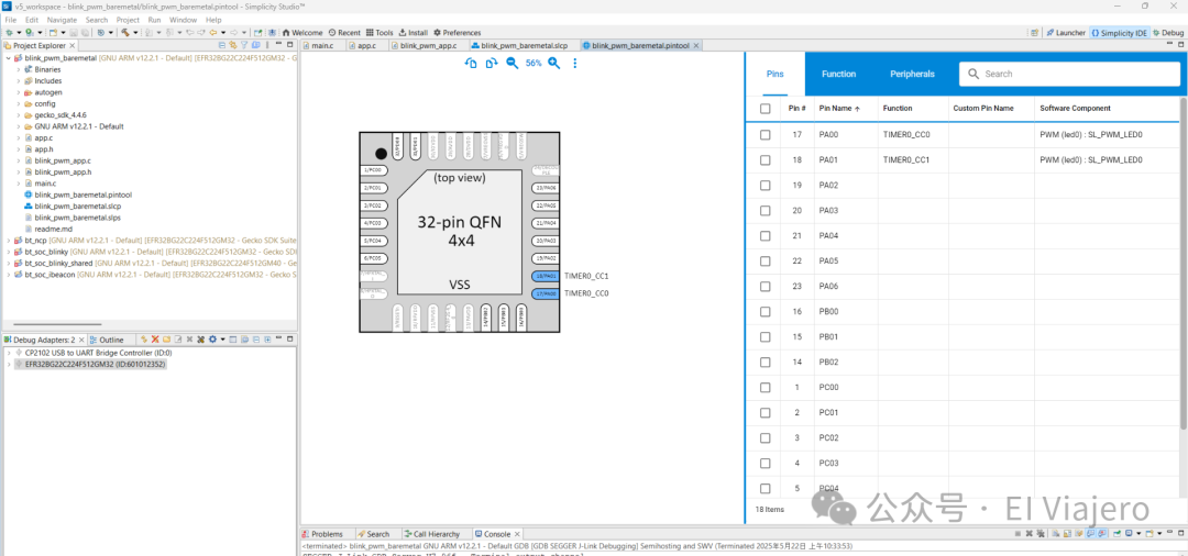
- Pin Tool: A graphical interface for assigning the physical pins of the chip to specific peripheral functions (such as USART TX/RX, PWM output, I2C SCL/SDA, GPIO interrupts, etc.) and checking for pin conflicts.
- Peripheral Configurator: Detailed parameter configuration for selected peripherals (such as TIMER, USART, ADC, I2C) (e.g., clock source, baud rate, PWM frequency, ADC resolution, etc.).
- Code Generation: Automatically generates initialization code, configuration file headers (such as
<span>sl_component_catalog.h</span>, defining the components included in the project), and peripheral instance files (such as<span>sl_pwm_instances.h</span>). - Integrated Toolchain: Built-in compiler (GCC ARM), debugger (GDB and Silabs J-Link/STK debugging interface), power profiler (Energy Profiler), and network analyzer (Network Analyzer).
2. Comparison with Other Development Approaches
Understanding the development approach of Simplicity Studio can be deepened by comparing it with other popular platforms:
-
Comparison with STM32 (STM32CubeMX / STM32CubeIDE):
- Configuration Starting Point and Process: STM32CubeMX is typically the first step in starting a project, used for graphical configuration of the MCU’s clock, peripherals, pins, and middleware, then generating a project framework that includes initialization code. Developers add application logic based on this framework. Its process leans more towards “configure first, then code, with configuration being mostly one-time generation”.
- The
<span>.slcp</span>file in Simplicity Studio plays a central role throughout the project’s lifecycle. Developers can adjust components and configurations at any time through it, and the IDE dynamically updates the relevant code. When starting a project, it is usually based on an example or template, which is then modified and configured. - IDE Integration: STM32CubeIDE integrates the functionality of CubeMX into the Eclipse environment, offering a similar experience to Simplicity Studio, but CubeMX can also be used as a standalone tool with other IDEs (such as Keil, IAR). Simplicity Studio, on the other hand, is a more closed and unified ecosystem.
- HAL/Driver Layer: STM32 provides HAL (Hardware Abstraction Layer) and LL (Low-Layer) drivers. Silabs provides the
<span>sl_</span>series high-level APIs and<span>emlib</span>low-level libraries, conceptually similar but differing in specific implementation and API style. -
Comparison with Texas Instruments (TI – e.g., Code Composer Studio + SysConfig):
- TI’s SysConfig tool shares many similarities with Simplicity Studio’s configuration philosophy; it is also a graphical configuration tool used to configure drivers, peripherals, pins, and software stacks, generating corresponding C code. SysConfig is typically used in conjunction with TI’s Code Composer Studio (CCS) IDE.
- Both emphasize simplifying low-level configurations through tools, allowing developers to focus on applications. SysConfig’s component-based approach is also quite prominent. Its design philosophy aims to provide a clear configuration layer, reducing the need for manually writing initialization code, which aligns with Simplicity Studio’s approach of managing components and configurations through the
<span>.slcp</span>file. -
Comparison with Espressif (ESP32 – ESP-IDF):
- ESP32 development primarily relies on ESP-IDF (Espressif IoT Development Framework), which is a software development framework based on FreeRTOS and lwIP.
- Configuration Method: ESP-IDF mainly uses the Kconfig system (invoked via the
<span>idf.py menuconfig</span>command to bring up a text menu interface) for configuring project features, components, and some driver parameters. This method may be more familiar to developers accustomed to Linux kernel configuration. - Pin/Peripheral Initialization: Specific pin assignments and peripheral initialization are more often completed in C code by directly calling the driver APIs provided by ESP-IDF, although there are configuration macros, the graphical pin assignment and integrated peripheral configuration tools are not as prominent as in the first two.
- IDE: The official recommendation is to use VS Code with the ESP-IDF plugin or a command-line-based development process. Its design philosophy focuses more on providing a flexible, code and build system-centric framework, giving developers higher control over the build process and component integration.
Simplicity Studio’s design philosophy leans towards providing a highly integrated “nanny-style” environment, especially when managing complex wireless protocol stacks and numerous configurable modules, maintaining project consistency and configurability through a unified <span>.slcp</span> file.
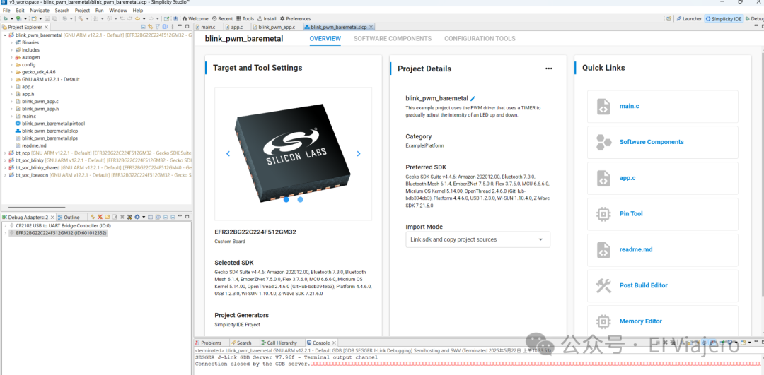
3. Analysis of EFR32 Project Code Structure (Using <span>blink_pwm_baremetal</span> as an Example)
A typical EFR32 bare-metal project (i.e., not using RTOS) usually contains the following key parts, as demonstrated by the <span>blink_pwm_baremetal</span> example:
Responsibilities: Initialize system-level services, protocol stacks (if any), and user applications. Then enter an infinite super-loop to schedule system and application tasks.
- Key Code Analysis (
<span>main.c</span>):#include "sl_component_catalog.h" // Generated by IDE, defines the components included in the project#include "sl_system_init.h" // System initialization function#include "app.h" // Application layer abstraction header file// ... Other conditionally included header files (e.g., power manager) ... int main(void) { sl_system_init(); // Initialize SDK components, drivers, clocks, etc. app_init(); // Call application layer initialization while (1) { sl_system_process_action(); // Periodic task processing for SDK components app_process_action(); // Periodic task processing for application layer // ... May include sl_power_manager_sleep() ... }} <span>sl_system_init()</span>: Encapsulates the initialization calls for all installed SDK components, which are defined by the<span>.slcp</span>file.<span>app_init()</span>: Transfers control to the application layer for initialization.<span>sl_system_process_action()</span>and<span>app_process_action()</span>: In the super-loop, the former ensures that internal SDK tasks (such as Bluetooth event handling) are executed, while the latter is left for the user to execute application logic.
-
<span>app.c</span>– Application Layer Abstraction/Bridging
- Responsibilities: Acts as a bridge between
<span>main.c</span>and specific business logic modules, maintaining the generality of<span>main.c</span>while delegating specific application initialization and processing logic to the next layer. - Key Code Analysis (
<span>app.c</span>):#include "blink_pwm_app.h" // Include header files for specific business modules void app_init(void) { blink_pwm_init(); // Call initialization for business module} void app_process_action(void) { blink_pwm_process_action(); // Call periodic processing for business module} - This layered design allows for complexity in application logic to be managed by including different business module header files and calling them in
<span>app.c</span>, without significantly modifying<span>main.c</span>.
<span>blink_pwm_app.c</span> (or Custom Business Module) – Actual Application Logic
- Responsibilities: Implements specific application functionality. In the
<span>blink_pwm_baremetal</span>example, this is controlling the PWM to achieve an LED breathing light effect. - Key Code Analysis (
<span>blink_pwm_app.c</span>):#include "sl_pwm.h" // PWM driver API#include "sl_pwm_instances.h" // PWM instances (generated by IDE based on configuration)#include "sl_sleeptimer.h" // Sleep timer API (for delays) // PWM duty cycle lookup table (LUT)uint8_t pwm_lut[] = { /* ... values from 0-100 ... */ }; void blink_pwm_init(void) { // Use the sl_pwm_led0 instance declared in sl_pwm_instances.h sl_pwm_start(&sl_pwm_led0);} void blink_pwm_process_action(void) { // Loop to change PWM duty cycle for breathing effect for (uint8_t i = 0; i < 100; i++) { sl_pwm_set_duty_cycle(&sl_pwm_led0, pwm_lut[i]); sl_sleeptimer_delay_millisecond(6); // ... (possible additional delay) ... } // ... (reverse loop) ...} <span>sl_pwm_instances.h</span>: This header file is crucial, typically containing declarations like<span>extern sl_pwm_instance_t sl_pwm_led0;</span>. The specific configurations of<span>sl_pwm_led0</span>(such as associated TIMER peripherals, output channels, pins, PWM frequency, polarity, etc.) are completed in the graphical configuration tool of Simplicity Studio and automatically generated by the IDE into the corresponding<span>sl_pwm_led0_config.h</span>(or similarly named) and initialization code.- Design Philosophy: Business logic modules directly use these peripheral instances managed and configured by the IDE without needing to concern themselves with the underlying initialization details.
4. Developing Custom PWM Output Process (Based on <span>blink_pwm_baremetal</span> Structure)
Assuming the goal is to develop a new PWM output control based on the structure of the <span>blink_pwm_baremetal</span> example (for instance, controlling another LED or a small fan).
-
Project Creation and Preparation:
- In Simplicity Studio, you can create a new project based on a bare-metal template or clone the existing
<span>blink_pwm_baremetal</span>example. - Ensure the correct target EFR32 chip or development board is selected.
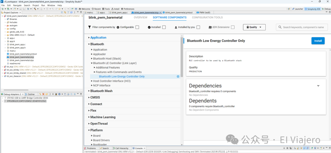
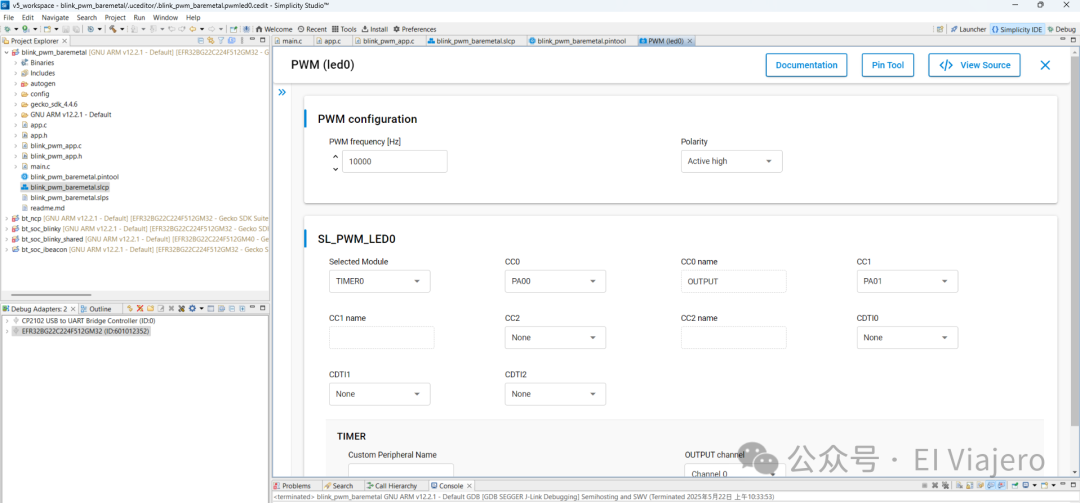
Adding and Configuring PWM Software Components:
- PWM Frequency (Hz): For example,
<span>10000</span>(10 kHz). - Polarity: Typically
<span>Active High</span>.
- Open the project’s
<span>.slcp</span>configuration file. - Navigate to the “SOFTWARE COMPONENTS” tab.
- Search for and install the “PWM” service (if not already installed).
- Create an instance for the new PWM output, for example, naming it
<span>custom_pwm</span>(the IDE may automatically generate an instance name like<span>sl_pwm_custom_pwm</span>). - Click on the newly created PWM instance and set it in the configuration panel on the right:
Pin Configuration (Pin Tool):
- In the configuration interface of the
<span>custom_pwm</span>instance, find the pin configuration section, or switch directly to the “PIN TOOL” tab at the top of the<span>.slcp</span>editor. - Key Steps:
- Result: The Pin Tool will automatically generate or update configurations in the background, such as defining
<span>SL_PWM_CUSTOM_PWM_PERIPHERAL</span>,<span>SL_PWM_CUSTOM_PWM_OUTPUT_CHANNEL</span>,<span>SL_PWM_CUSTOM_PWM_OUTPUT_PORT</span>,<span>SL_PWM_CUSTOM_PWM_OUTPUT_PIN</span>, etc. in the<span>sl_pwm_custom_pwm_config.h</span>(or similarly named file). At the same time, a declaration of the<span>sl_pwm_custom_pwm</span>instance will also appear in<span>sl_pwm_instances.h</span>.
- In the Pin Tool’s peripheral list, find an available TIMER peripheral (such as
<span>TIMER1</span>,<span>TIMER2</span>, etc., avoiding conflicts with the TIMER used by<span>sl_pwm_led0</span>, unless that TIMER supports independent PWM on multiple channels and the channel is unoccupied). - Select an available output channel (CC Channel) of that TIMER.
- In the chip pinout diagram, find an available GPIO pin you want to use for PWM output.
- Drag or assign the selected TIMER channel function to this GPIO pin.
Adding Delay Functionality (Sleep Timer):
- If the application requires precise delays, ensure the “Sleep Timer” component is installed in the project (usually present by default in many examples).
Writing Business Logic Code:
- Create a new
<span>.c</span>file (e.g.,<span>my_custom_pwm_logic.c</span>) and the corresponding<span>.h</span>file. - In
<span>my_custom_pwm_logic.c</span>:#include "sl_pwm.h"#include "sl_pwm_instances.h" // This will include the declaration of sl_pwm_custom_pwm#include "sl_sleeptimer.h"#include "my_custom_pwm_logic.h" // Your own header file // You can define new LUT or control parameters here// static uint8_t custom_duty_cycle = 50; // Example: fixed duty cycle void my_custom_pwm_init(void) { sl_pwm_start(&sl_pwm_custom_pwm); // Start the new PWM instance // Optional: set initial duty cycle // sl_pwm_set_duty_cycle(&sl_pwm_custom_pwm, custom_duty_cycle);} void my_custom_pwm_process_action(void) { // Implement custom PWM control logic here // For example: change duty cycle based on some input, or implement different blinking patterns // static uint8_t new_duty = 0; // new_duty = (new_duty + 10) % 101; // Simple 0-100 loop // sl_pwm_set_duty_cycle(&sl_pwm_custom_pwm, new_duty); // sl_sleeptimer_delay_millisecond(100);} // You can add other control functions, for example: void set_my_custom_pwm_duty(uint8_t duty) { sl_pwm_set_duty_cycle(&sl_pwm_custom_pwm, duty);} - In
<span>my_custom_pwm_logic.h</span>, declare functions like<span>my_custom_pwm_init()</span>and<span>my_custom_pwm_process_action()</span>.
Integrating into Application Layer (<span>app.c</span>):
- In
<span>app.c</span>, include<span>#include "my_custom_pwm_logic.h"</span>. - Modify
<span>app_init()</span>:void app_init(void) { // blink_pwm_init(); // Retain original example initialization (if needed) my_custom_pwm_init(); // Add new module initialization} - Modify
<span>app_process_action()</span>:void app_process_action(void) { // blink_pwm_process_action(); // Retain original example processing (if needed) my_custom_pwm_process_action(); // Add new module processing}
Build, Flash, and Debug:
- In Simplicity Studio, click “Build” (hammer icon).
- If there are no compilation errors, click “Debug” or “Run” to flash the firmware onto the EFR32 device.
- Use the debugger to step through the code and observe variable states.
- Connect an oscilloscope to the GPIO pin configured for
<span>sl_pwm_custom_pwm</span>to verify that the PWM waveform meets expectations (frequency, duty cycle variations, etc.).
5. Conclusion
The EFR32 development ecosystem provides a highly integrated and configuration-driven development model through Simplicity Studio. This approach has advantages for managing SoC projects that include complex wireless protocol stacks and numerous peripherals, allowing developers to quickly prototype and iterate. Its design philosophy aims to abstract low-level details through tools, enabling developers to focus more on application layer innovation. Although its learning curve and operational habits differ from other platforms (such as STM32’s CubeMX or ESP32’s ESP-IDF), once familiar, its componentization and configurability can significantly enhance development efficiency for specific types of projects. Through the aforementioned development process exemplified by PWM, one can appreciate its design philosophy of “configuration over coding (for hardware setup)”, especially in scenarios requiring rapid adaptation to different hardware or reusing existing software components, where the convenience of this method is particularly prominent.