The ECG acquisition includes two parts: analog acquisition and digital processing. This design captures the human ECG signal using AgCl electrodes and a three-lead ECG acquisition line. The signal is then processed through a preamplifier circuit, bandpass filter circuit, and a 50 Hz twin-T notch filter before being amplified by the main amplifier circuit and level-shifting circuit to control the amplitude of the ECG signal within the A/D acquisition range of the STM32. The STM32 sets the A/D sampling frequency using a timer and processes the obtained digital signal using a mean filtering method.
The core of the control module is the STM32F103VET microcontroller, which is a high-performance, low-cost, and low-power enhanced microcontroller produced by STMicroelectronics. It uses the latest ARM Cortex-M3 architecture with a maximum operating frequency of 72 MHz, 512 kB of program memory, 64 kB of RAM, 8 timers/counters, two watchdogs, and one real-time clock (RTC). The on-chip communication interfaces include two I2C, three SPI, five USART, one USB, one CAN, one SDIO, and it integrates three ADCs and one DAC, with 100 I/O ports. The pin arrangement diagram of the main microcontroller is shown in Figure 1.
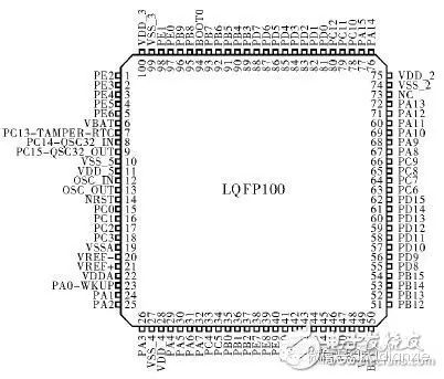
Figure 1: STM32F103VET Microcontroller Pin Arrangement
The preamplifier circuit is the front end of analog signal acquisition and is the key to the entire circuit design. It must accurately capture the weak ECG signal from the human body while minimizing interference signals. Since the ECG signal is a differential signal, the circuit should adopt a differential amplification structure while requiring the system to have high common-mode rejection ratio, high input impedance, and low drift characteristics. Therefore, selecting the appropriate operational amplifier is crucial. Here, the AD620 instrumentation amplifier is chosen for preamplification, which has high accuracy, low noise, low input bias current, and low power consumption, making it suitable for ECG monitoring devices and other medical applications. The amplification factor of the AD620 is determined by the feedback resistor between pins 1 and 8, with gain G=49.4 kΩRG+1. Since the ECG signal contains a significant DC component, the amplification factor of the preamplifier circuit cannot be too high; here, an amplification of about 10 times is chosen, so the feedback resistor R6 is set to about 5 kΩ. To enhance the circuit’s common-mode rejection capability, an OP07 is used to detect the common-mode signal on R10 and R4, driving the shielding layer of the lead wire to eliminate distributed capacitance. Simultaneously, another OP07 operational amplifier, along with R5, C3, and R7, forms a right-leg drive circuit. The common-mode signal detected on R10 and R4 is inverted and amplified, then fed back to the person’s right leg through R7, further suppressing the common-mode signal and 50 Hz power line interference. Here, the right-leg drive has a feedback path for AC interference, which may pose a risk to human health; therefore, proper insulation measures must be taken, and the protective resistor R7 should be as large as possible, set above 1 MΩ. Moreover, the instability of the system power supply also significantly impacts ECG signal acquisition. Therefore, in this system, two 0.1μF and 10μF capacitors are connected in parallel to the power pins of all operational amplifiers to improve system stability. The circuit diagram of the preamplifier circuit is shown in Figure 2.
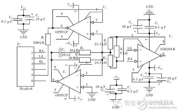
Figure 2: Preamplifier Circuit
The ECG signal output from the preamplifier circuit still contains significant DC components and EMG signals, baseline drift, and other interference elements. The useful ECG signal to be collected is in the range of 0.03 to 100 Hz. Therefore, a reasonable filter needs to be designed to allow signals within this range to pass through sufficiently while maximizing attenuation of signals outside this range. Here, two OP07 operational amplifiers are used to form a second-order active high-pass filter and low-pass filter. The high-pass filter consists of C11, C17, R7, and R10 with a cutoff frequency of f1≈0.03 Hz, while the low-pass filter consists of R8, R9, C10, and C13 with a cutoff frequency of approximately f2≈100 Hz. The circuit of the system bandpass filter is shown in Figure 3.
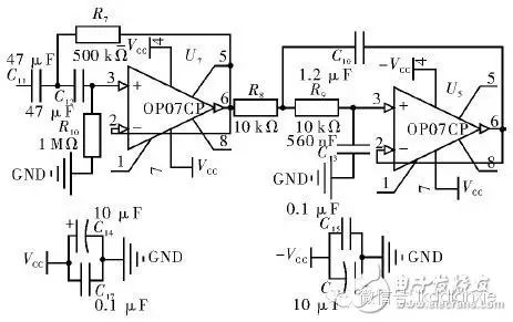
Figure 3: Bandpass Filter
The amplitude of the ECG signal is approximately 0 to 4 mV, while the input level requirements for STM32 AD conversion are 3.3 V. Therefore, to enable the microcontroller to process the acquired ECG signal, the acquired analog signal needs to be amplified by 800 to 1,000 times. The preamplifier circuit has amplified it by 10 times; theoretically, the main amplifier circuit should amplify it by about 100 times. To ensure that the signal is not distorted, single-stage amplification is generally not more than 10 times. Therefore, a two-stage amplification method can be adopted to achieve a 100-fold amplification effect. U9 is fixed at 10 times amplification, and U11’s feedback resistor is an adjustable resistor, allowing for adjustment through a potentiometer to achieve the 100-fold amplification effect. Additionally, since the STM32 microcontroller’s A/D acquisition cannot sample negative levels, a level-shifting circuit, as shown in U7, is designed to raise the ECG signal above the 0 level, facilitating acquisition by the microcontroller.
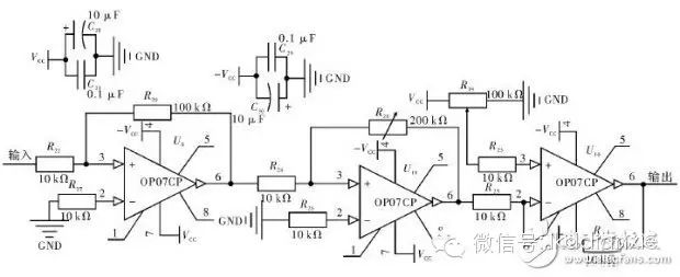
Figure 4: Main Amplifier Circuit
Editor’s Comment: This design implements a small ECG acquisition device with STM32 as the control core, using AD620 and OP07 for analog signal acquisition. The circuit performance is stable and meets the requirements for home monitoring and pathological analysis. The entire system design is simple, cost-effective, and has certain medical value.