To not miss my updates, remember to check the public account in the upper right corner and set it as a star, and give me a star!

Now let me teach you step by step how to make it:
Step One
Waterproofing

https://www.digikey.ca/product-detail/en/bud-industries/PTK-18422-C/377-2758-ND/8602492
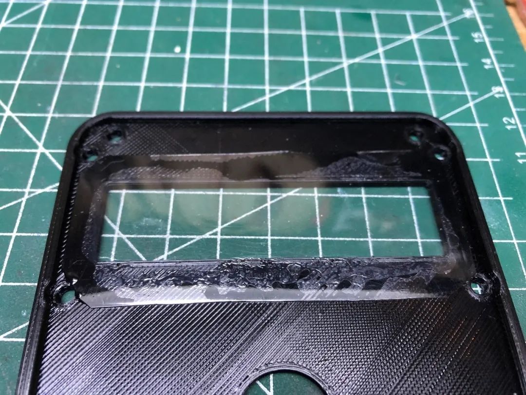
Step Two
Printing the Shell

Darwin custom sweatshirt, sister Ni’s universal multimeter, click to draw!
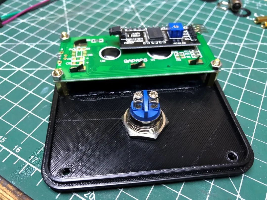
Step Three
Install the LCD Screen and Buttons

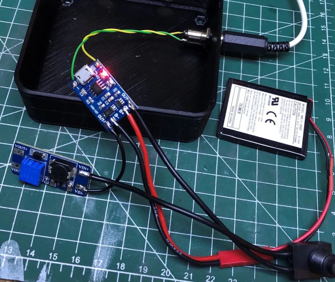
Step Four
Power Supply and Charging Circuit


Since the custom shell is fixed with a few screws, and I don’t want to open the shell every time I need to charge it, I use a 3.5mm headphone jack.
Step Five
Charging Cable

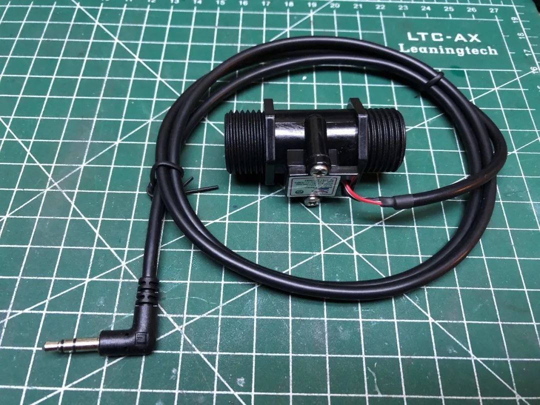
Step Six
Modifying the Flow Sensor

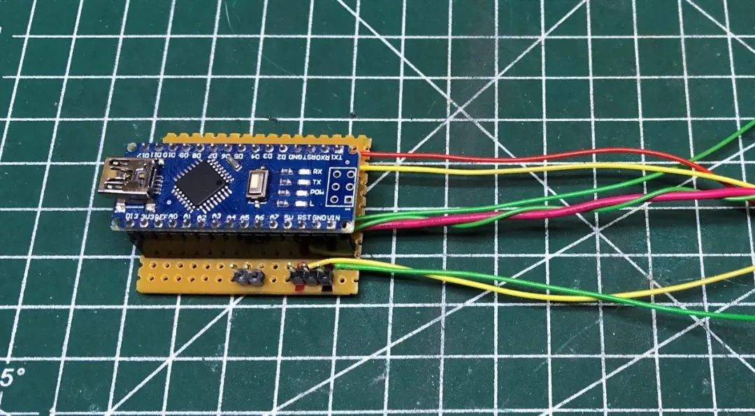
Step Seven
Connecting Everything

Step Eight
Code

if((millis() - previousMillis) >= 1000) { previousMillis = millis(); toggleLED(); }
Darwin custom sweatshirt, sister Ni’s universal multimeter, click to draw!
If you want to change the water cost or change the units, you can modify it in the code.
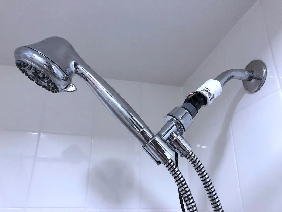
Step Nine
Assembly and Testing


Darwin custom sweatshirt, sister Ni’s universal multimeter, click to draw!
Compiled by:Wang Tongxue

More Practical Project Recommendations:
STM32 IoT Smart Home Project
Project Sharing | Hand-in-Hand Face Recognition with MATLAB + Raspberry Pi
Raspberry Pi + Compute Stick 2 Complete Real-Time Face Recognition Project
Building a Cloud Computing Platform for Embedded Development Boards
STM32 Achieves the Simplest Air Mouse
Arduino Rubik’s Cube Robot
STM32 Version “AI Soul Painter”
STM32 Electronic Photo Album Production
STM32 + DDS Homemade Signal Generator
Using Raspberry Pi and Web Interface to Remotely Control Home Appliances
STM32 “Cloud” Music Player
Remote Monitoring with Raspberry Pi
Design of Neon Tube Clock Based on STM32
Homemade FPGA Minimal System Board (PCB can be directly made)
Building NAS with Raspberry Pi 4 to Easily Network Hard Drives
ESP32 Car Practical Sharing of Software and Hardware
Only 79 Lines of Code to Complete Creative Gesture Recognition
IoT + Electronic Ink Screen Can Create Custom Displays
Build a Pathfinding Robot Worth Over a Thousand with Just Dozens of Dollars
Stereoscopic 3D Holographic Display, Visual Persistence POV Project
DIY Gesture Recognition Module
Practical Small Designs You Can DIY with No Foundation
Raspberry Pi Creates a Smart Doorbell + Smart Door Lock with Video
Strange! My Development Board Can Play Games Automatically
Homemade Breathing Machine
ESP8266 + Zigbee Network Transformation of Wall Switch
Wireless Home Monitoring System
DIY Bionic Arm, A Tool to Free Your Hands
Handmade Air Purifier, All Design Data Open Source
Tech Toy: Bluetooth Artillery That Can Be Controlled Remotely
Using ST Sensors to Create a LittleBee Monitoring System to Let Bees “Talk”
Homemade Cat Toy
STM32 + Raspberry Pi Achieves 6s Rubik’s Cube Robot
Blindly Modifying Drone Controller, DIY “Foam” Drone
Making a Smart Relay Without Arc Using STM32
Making a Practical New Model Necklace with Just 5 Components
The Simplest Method for Measuring Heart Rate (Suitable for Secondary Development)
Cracking a Magnetic Levitation Globe
The Amazing Light Can Transmit Video? Revealing the Production Process
STM32 Homemade Smart Watch 60FPS Animation
Paying Tribute to the Classic Radio, Observing the Production Process
DIY Third Eye: “Special” Glasses with Bluetooth/OLED/Lens Functionality
Homemade Solar Charger That Tracks Maximum Power Point
No MCU Night Vision Goggles, Just Connect the Wires
Recommended Reading: