This article introduces how to drive an ESP32 OLED display using .Net nanoFramework. We will start from the basics and gradually delve deeper, enabling you to understand and implement the entire process. Whether you are a beginner or an experienced developer, this article will be helpful to you.
1. Hardware Preparation
1.1 ESP32 Development Board
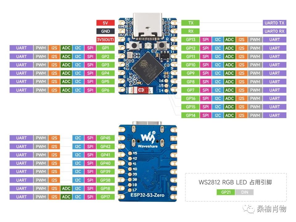
The ESP32 development board we are using is the Weixue ESP32-S3-Zero, which is very compact but powerful. This development board uses the ESP32-FH4R2 system-on-chip (SoC), which integrates low-power Wi-Fi and BLE5.0, with 4MB of Flash and 2MB of PSRAM. It also features a hardware encryption accelerator, random number generator (RNG), HMAC, and digital signature module to meet the security requirements of IoT.
Although the development board is small, it offers a considerable number of pins. The following image shows the pinout of the ESP32-S3-Zero:
1.2 OLED Display
The OLED display we are using is the previous 0.96-inch yellow-blue dual-color OLED module, which employs the SSD1306 driver chip, supports I2C communication, and has a resolution of 128×64, making it very suitable for small displays. It has a total of four pin interfaces: 3.3V positive VCC, negative GND, SCL clock line, and SDA data line.
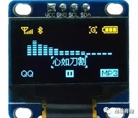
This display can be considered a memory for a generation, as it was used in small electronic devices like MP3 players. Although it has been phased out, its display quality is still quite good, and it remains widely used in hardware development and learning fields, with a very low price of about 10 yuan.
2. Hardware Connection
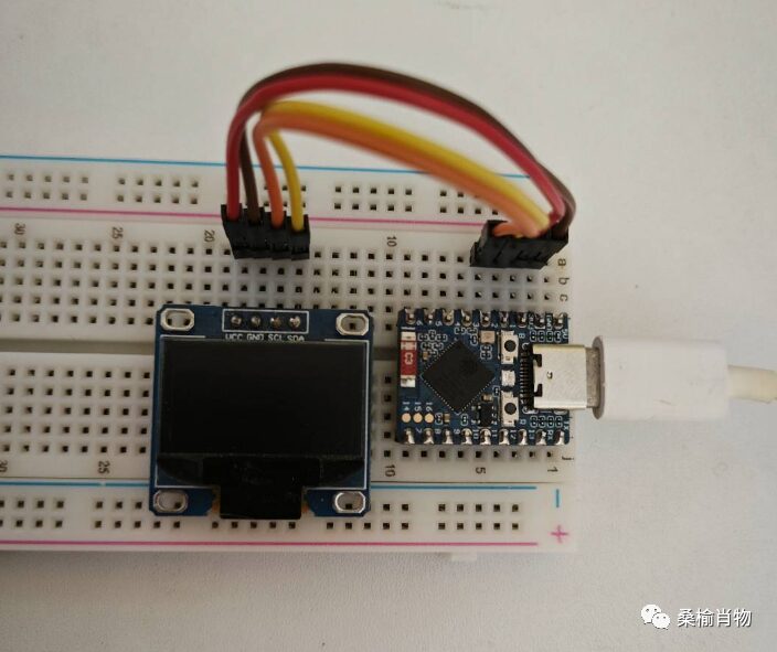
The hardware connection is very simple. First, for power supply: just connect the OLED’s VCC to the ESP32’s 3.3V pin and GND to the ESP32’s GND pin. Then connect SCL and SDA to the ESP32 pins that support I2C communication; we choose GP1 and GP2 here.
3. Software Preparation
There is no need for excessive introduction to the software preparation here; you can refer to the previous article “Quick Start .NET nanoFramework Development for ESP32-Pico Applications.” This article introduces how to install the .NET nanoFramework development environment and how to use the nanoff tool for firmware flashing.
It is important to note that we are using the ESP32-S3-Zero development board, so when flashing the firmware, you can choose ESP32_S3 or ESP32_S3_BLE.
nanoff --target ESP32_S3_BLE --serialport COM5 --update4. Writing Code
4.1 Dependency Installation
Open Visual Studio and create a new .NET nanoFramework application, installing the following package dependencies via NuGet:
•nanoFramework.Hardware.Esp32•nanoFramework.Iot.Device.Ssd13xx•nanoFramework.System.Collections
4.2 Drawing Methods
The SSD1306 driver provides some drawing methods that allow you to draw at the pixel level on the screen:
•DrawPixel(…): Draw a pixel•DrawHorizontalLine(…): Draw a horizontal line•DrawVerticalLine(…): Draw a vertical line•DrawFilledRectangle(…): Draw a filled rectangle•DrawBitmap(…): Draw a bitmap•DrawString(…): Draw a string using a preset font
Using these methods, you do not need to worry about the technical details of the driver used to display your drawing commands.
Additionally, regarding font settings, it is important to note that due to limited device resources, fonts need to be converted into hexadecimal encoding using dot matrix data for use in the code. Here we use the BasicFont font, which can be found in the official examples.
For more information on dot matrix fonts, please stay tuned for future articles where I will introduce how to create dot matrix fonts.
4.3 Writing Code
For the ESP32 device, we need to configure the device pins according to our wiring. Here we need to configure the I2C SCL and SDA pins, as shown in the following code:
Configuration.SetPinFunction(1, DeviceFunction.I2C1_DATA);Configuration.SetPinFunction(2, DeviceFunction.I2C1_CLOCK);Then we need to create an I2cDevice object for I2C communication, passing it to the SSD1306 driver. The code is as follows:
using Ssd1306 device = new Ssd1306(I2cDevice.Create(new I2cConnectionSettings(1, Ssd1306.DefaultI2cAddress)), Ssd13xx.DisplayResolution.OLED128x64);Finally, we can control the OLED display through the SSD1306 driver:
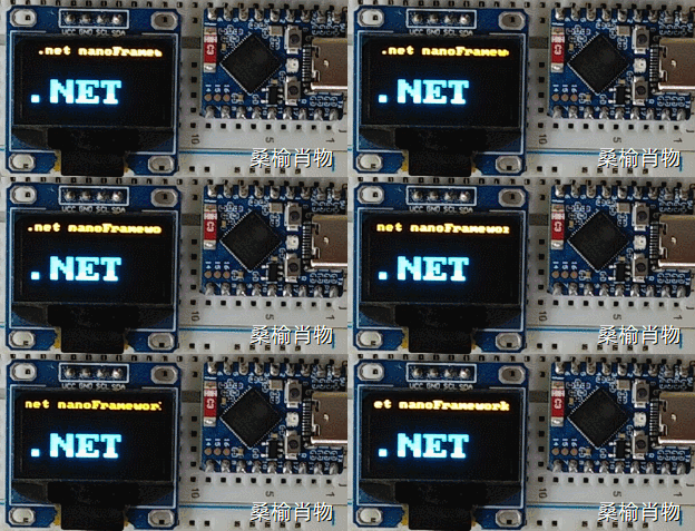
device.ClearScreen();device.Font = new BasicFont();device.DrawString( 0, 0, "nanoFramework", 1);device.DrawString(0, 32, ".NET", 3);device.Display();Once the code is deployed to the ESP32 development board, you will see the desired content displayed on the OLED display.
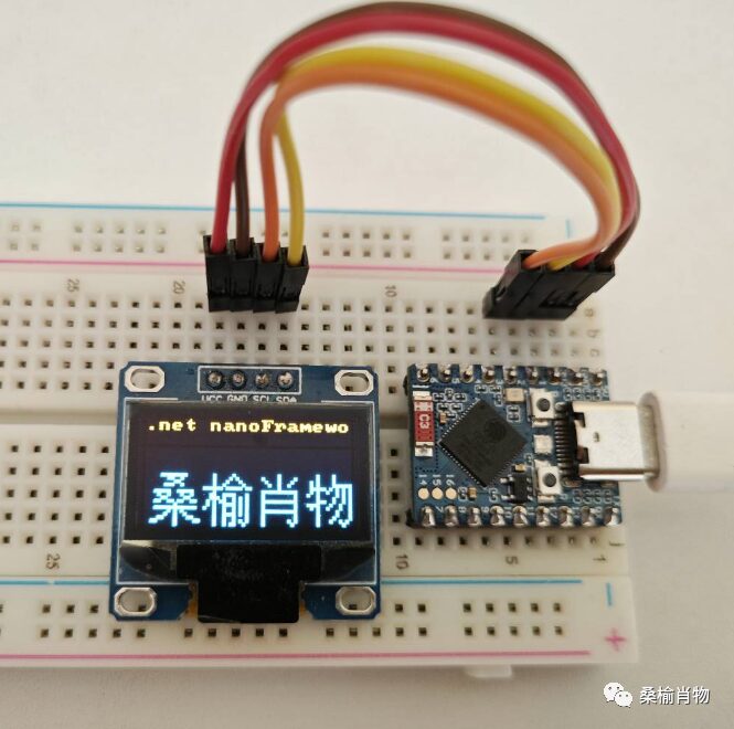
For displaying longer strings, we can use scrolling to show the content, as shown in the following code:
// Scroll to display more content
string str = ".net nanoFramework  ";// Add 2 spaces to ensure display effect
int strWidth = device.Font.Width * str.Length; // Calculate original string width
int ledWidth = 128; // Device width
int showTimes = 5; // Number of times content needs to be displayed
int showWidth = strWidth * showTimes - ledWidth; // Calculate width to shift content left
string showStr = "";// Increase showStr + str until greater than showWidth
do{
    showStr += str;
}while (device.Font.Width * showStr.Length < showWidth);
for (int i = 0; i < showWidth; i++) {
    // Clear scrolling area
    device.ClearDirectAligned(0, 0, 128, 16);
    // Adjust starting position of string based on conditions
    int x = i > strWidth ? i - strWidth : i;
    device.DrawString(-x, 0, showStr, 1); // Move starting position of string left
    device.Display();
    Thread.Sleep(10);
}
5. Conclusion
This article introduced how to drive an ESP32 OLED display using .Net nanoFramework. We started from the basics and gradually delved deeper, enabling you to understand and implement the entire process. Whether you are a beginner or an experienced developer, this article will be helpful to you.