 New friends, click the blue text above to follow me 01 Drone Upgrade Modification Guide
✈️ Is your drone still just flying aimlessly? Watching others’ drones automatically avoid obstacles, land accurately, and transmit high-definition images in real-time, are you envious? 🤤
Don’t worry! Today’s article “Installation Manual” will teach you step by step how to equip your beloved drone with “three essential tools“: an infrared sensor, GPS, and video transmission system! Transform from a “pilot” to a “geek”!
02 Core Modification Principles
01 Core Idea: Distinguish between the “input” and “output” of the “brain”
Imagine, the drone’s flight controller (Flight Controller) is its “🧠 brain”. The devices we add serve two main purposes:
Provide “input” information to the brain 👉: Allow the flight controller to perceive the world. For example: “How high am I from the ground?” (Infrared), “Where am I?” (GPS).
Allow the brain to “output” commands 👊: Enable the flight controller to control other devices. For example: “Camera, take a picture!” (Mission camera).
Remember this logic, everything else will become simple! 😁
03 Infrared Sensor Installation Guide
02 “Perception Expert” Infrared Sensor: Let the drone “feel”
🤔 What is it used for? Equip the drone with a “smart ruler” 📏! It allows precise measurement of the distance to the ground or obstacles, enabling accurate landings, indoor altitude holding, obstacle avoidance, and other cool features.
🛠 How to install? (The key point is here! 😎)
Connection Mnemonic: “TX connects to RX, don’t forget the power!”
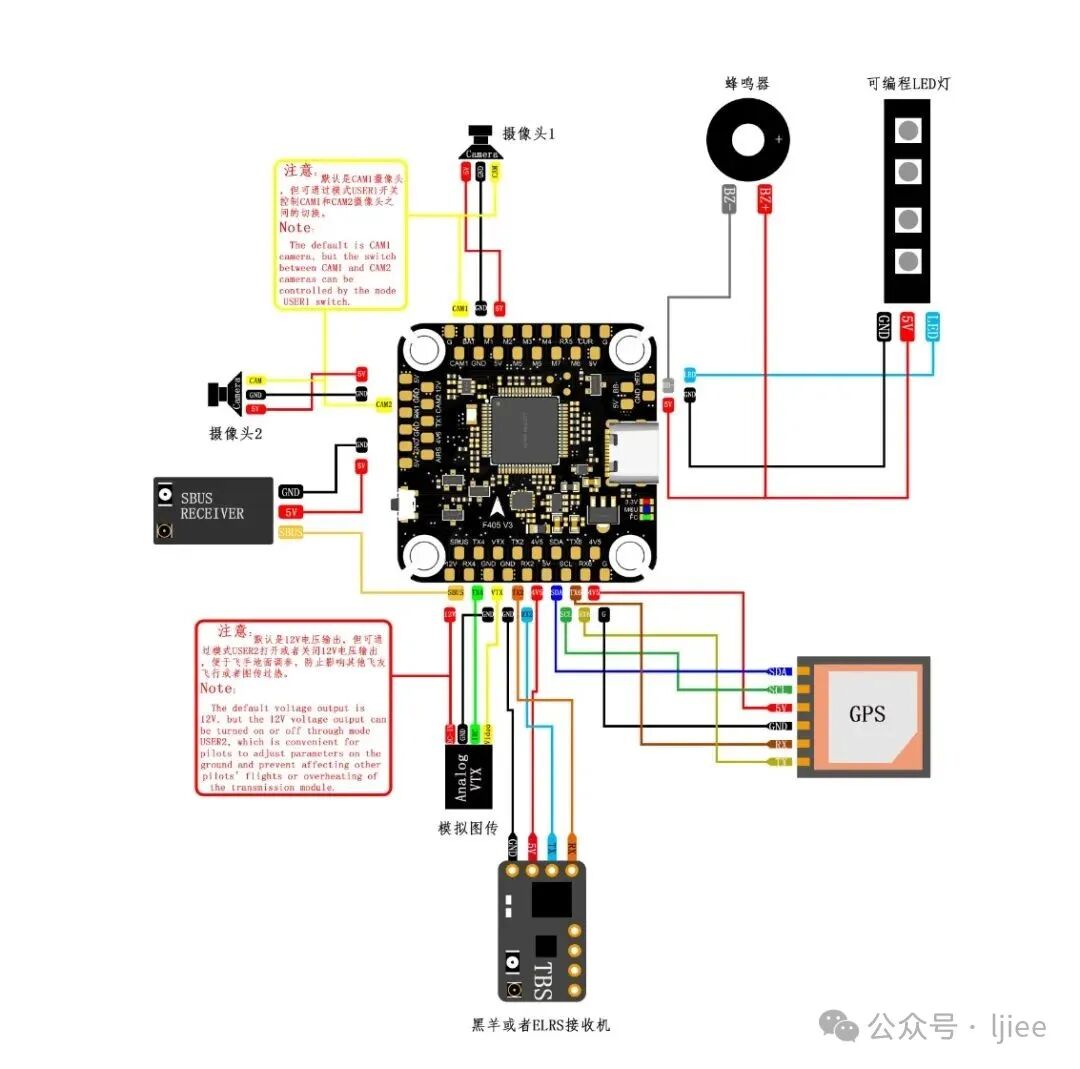
Find the interface: Look for an available serial port (UART) on the flight controller, such as TELEM2 or SERIAL4. Wiring: Connect the sensor’s TX line to the RX pin of the flight controller’s serial port, and the RX line to the TX pin (if the sensor does not need configuration, it can be left unconnected), VCC and GND connect to power and ground. 🧵 Software configuration (magic moment): Use ground station software (like Mission Planner) to tell the flight controller: “Hey! I connected a rangefinder to that port!”
PS: The entire process is divided into three steps
- Hardware Connection: Physically connect the infrared sensor to the corresponding port on the flight controller.
- Software Configuration: Set the sensor type, data source, and trigger actions in the ground station software (like Mission Planner, QGroundControl).
- Logical Application: Write or set how the flight controller uses the infrared sensor data to control the drone (e.g., trigger landing, obstacle avoidance, or specific tasks).
Connection Steps:
- Power Off: Make sure to disconnect the drone battery from the flight controller.
- Consult Documentation: Carefully read your flight controller pinout diagram and infrared sensor manual.
- Corresponding Connections:
Sensor <span>VCC</span> -> Flight Controller <span>5V</span> (or <span>3.3V</span>, depending on the sensor requirements)
Sensor <span>GND</span> -> Flight Controller <span>GND</span>
Sensor <span>TX</span> -> Flight Controller serial port’s <span>RX</span> (Note: TX connects to RX)
Sensor <span>RX</span> -> Flight Controller serial port’s <span>TX</span> (if no commands need to be sent to the sensor, this line can be left unconnected)
(For I2C) Sensor <span>SDA</span> -> Flight Controller <span>I2C Data</span>
(For I2C) Sensor <span>SCL</span> -> Flight Controller <span>I2C Clock</span>
Finally, for software configuration, after the hardware connection is complete, you need to tell the flight controller which port to read data from and the type of data.
Here is a key reminder to configure serial port parameters:
- Go to Config/Tuning -> Full Parameter List.
- Find the parameters related to the hardware serial port you connected. For example, if you connected to
<span>SERIAL4</span>: <span>SERIAL4_PROTOCOL</span>: Set to<span>9</span>(RangeFinder). This tells the flight controller that this port is connected to a rangefinder.<span>SERIAL4_BAUD</span>: Set to the baud rate of your infrared sensor communication (check the sensor manual, common values are 9600 or 115200 🤪).
Configure Sensor Type:
- Continue to search for the following parameters in the full parameter list:
<span>RNGFND_TYPE</span>: Set to the model of your infrared sensor. For example:<span>1</span>= Analog<span>8</span>= LightWare Serial (common brand)<span>10</span>= MaxBotix Serial<span>11</span>= Benewake TFmini / Lite (common low-cost infrared radar)- … (the list is long, choose the corresponding value based on your specific sensor model 😏). If unsure, refer to the ArduPilot official documentation or the sensor manufacturer’s instructions.
04 GPS Module Installation Guide
03 “Navigation King” GPS: Let the drone “find its way”
🤔 What is it used for? The drone’s “Global Positioning System” 🌍! Without it, the drone cannot know its latitude and longitude, and thus cannot achieve core functions such as autonomous navigation, precise hovering, and automatic return.
🛠 How to install?
Connection Mnemonic: “Align the interface, just plug it in!” (Yes, it’s that simple! 👻)
Find the interface: The dedicated port marked GPS on the flight controller! That’s it! Wiring: 99% of universal GPS modules have foolproof designs, just plug them in! Power and communication are handled by one line, it’s simply a “nanny-level” design. 🔌 Software configuration: Basically, no configuration is needed! The flight controller is pre-configured to automatically recognize it upon power-up. This is the “standard configuration” treatment!
🎯 Effect: After powering on, patiently wait for the number of satellites on the screen to gradually increase until it indicates GPS Lock (successful positioning), and your drone officially has a “global perspective”!
PS:Similarities with the infrared sensor:
- Both connect via UART.
- Both require setting protocol and baud rate in the ground station software.
Differences from the infrared sensor:
- Fixed Interface: The flight controller usually has a dedicated GPS port (marked as
<span>GPS</span>or<span>GPS1</span>). This port not only provides serial communication but also powers the GPS module and is directly compatible with common GPS modules (like Here series, M8N series, etc.). - Fixed Protocol: GPS almost universally uses NMEA or UBX (u-blox chip specific) protocols. The flight controller automatically parses these protocols.
- Simple Configuration: In most cases, you do not need to manually set parameters. As long as the hardware connection is correct, the flight controller will automatically recognize it and start searching for satellites upon power-up. The flight controller defaults the first serial port (
<span>SERIAL1</span>) for GPS, and its protocol parameter (<span>SERIAL1_PROTOCOL</span>) is defaulted to<span>5</span>(GPS).
 05 Video Transmission System Installation Guide
04 “Eyes and Live Broadcast” Video Transmission System: Let you “see”
🤔 What is it used for? It transmits the images seen by the drone’s camera in real-time to your ground screen or goggles. It is the drone’s “live broadcast room” 📹, allowing you to achieve first-person view (FPV) flying.
🛠 How to install?
Connection Mnemonic: “Each returns home, each finds their mother!” (Because it is an independent system!)
Camera -> Video Transmission Transmitter (VTX): Connect using a video cable. VTX -> Power: Directly powered from the battery or ESC, VTX is a “power-hungry device”. Flight Controller -> VTX: The flight controller only uses a thin signal wire to overlay OSD information (battery level, altitude, speed, etc.) onto the video signal like a “bullet screen”. 🗒️ Software configuration: Mainly design what “bullet screen” (OSD information) you want to see on the screen in the ground station.
🎯 Effect: Turn on the display device, tune to the channel, and you can overlook the world from the drone’s perspective! Awesome!
PS:Loading the Camera
Here, the “camera” is divided into two types, and their loading methods are vastly different:
- FPV Camera: Used for real-time transmission of first-person view images.
- Mission Camera: Used for taking photos, recording videos, gimbal control, or computer vision (such as target tracking, mapping).
A. FPV Camera
- Differences from the infrared sensor:
- Does not connect directly to the flight controller: The video transmission system is an independent subsystem.
- Signal Flow: Camera -> Video Transmission Transmitter (VTX) -> (via radio waves) -> Ground Receiver -> Display or FPV Goggles.
- Role of the Flight Controller: The flight controller usually only sends OSD (On-Screen Display) data (such as altitude, speed, battery level, flight mode) to the VTX through a simple IO port. The OSD chip overlays this data onto the video signal, which is ultimately displayed in the image you see.
- Loading Process:
- Connect the camera’s video line to the VTX’s video input port.
- Power the camera and VTX (usually directly from the power distribution board or BEC).
- Connect the flight controller’s OSD signal line (usually the TX pin) to the VTX’s OSD data input port (if the VTX supports it).
- Enable the OSD function in the ground station.
B. Mission Camera (with gimbal control)
- Similarities with the infrared sensor:
- Both may communicate with the flight controller via UART or I2C.
- Differences from the infrared sensor:
- More Complex Interaction: The flight controller not only receives data but also sends commands. For example, sending commands to the camera to take a picture, start recording, change modes, etc. via MAVLink protocol.
- Standardized Protocol: Advanced cameras (like DJI Zenmuse series, Sony QX1, etc.) typically use the MAVLink protocol’s
<span>CAMERA</span>or<span>GIMBAL</span>command set for control. - Trigger Purpose: The logic for controlling the camera is not for flight control but for executing tasks.
06
🌈 Ultimate Comparison Summary
| Device | Flight Controller Perspective | Connection Difficulty | Configuration Mnemonic | Achievement |
| Infrared Sensor | Input Information (How high am I?) | ⭐⭐☆ | Find the serial port, change the protocol | Achieve “tactile perception” 🦾 |
| GPS | Input Information (Where am I?) | ⭐☆☆ | Just align and plug it in | Unlock “global navigation” 🗺️ |
| Video Transmission System | Output Information (Overlay data onto the image) | ⭐⭐☆ | Independent power supply, OSD overlay | Start “first-person” live streaming 👀 |

 Scan the QR code for more exciting content