【Click the above「blue text」 to follow the DF Maker Community and become a tech enthusiast】

Old friends should know that we have previously recommended many watch-related projects (there is a collection at the end), and the feedback has been quite good.
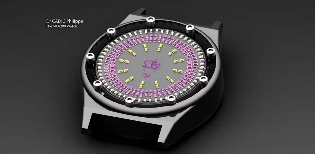
This week we are recommending another BCD watch project.
What is BCD?
BCD stands for Binary-Coded Decimal, which uses 4-bit binary numbers to represent the digits 0-9 in a decimal number. It is a form of binary digital encoding, using binary-coded decimal.
Since most watches in our daily lives are in decimal format, this unique binary representation of time can be difficult for the average person to understand and may require some time to convert, making it seem more “geeky”.
Step 1: Function Introduction
When you long-press the button, the watch enters setup mode. First, the hour indicator will blink, indicating that it is in hour setting mode, and you can increase the value by pressing the button.
When you long-press the button again, it will enter minute setting mode, and the minute indicator will start blinking. Pressing the button can increase the minute value.
To exit the setup mode, long-press the button again, and after the long press, it will display the time normally.
Step 2: PCB Design
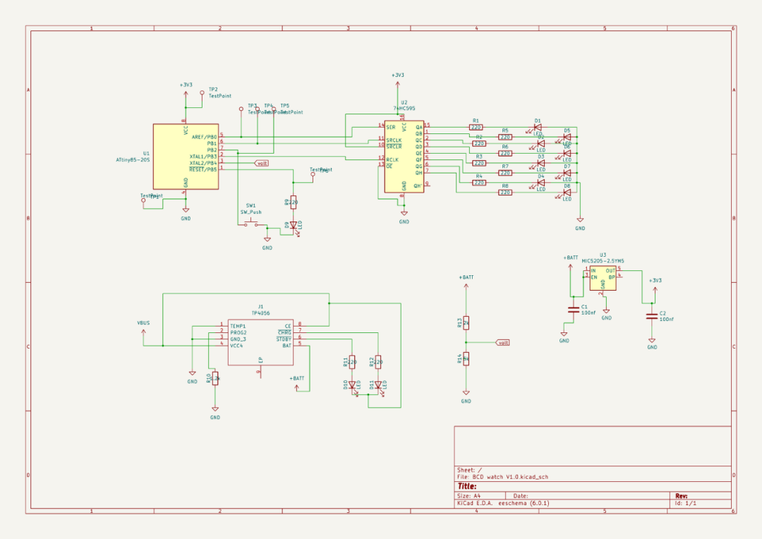
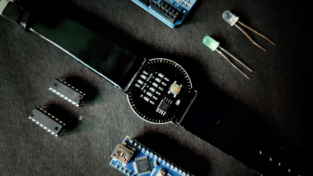
First, design the schematic in KiCad software, using the ATtiny85 as our controller.
The ATtiny85 has few pins, so we used a 74HC595 shift register to increase the LED pins. We also added a button to display and set the time. For charging, we used a TP4056 circuit, which can handle the charging of lithium batteries.
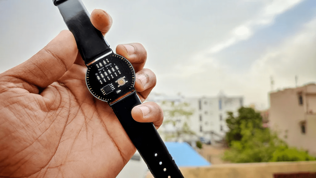
After completing the schematic, we placed it on the PCB, and you can see that the PCB is circular with two slots for inserting the watch strap.
KiCad has a 3D viewer for PCBs, so we can verify what our PCB will look like, ensuring all components and vias are in the correct position. We can export this STL file for further use in 3D modeling.
All PCB files are open source and can be downloaded from the GitHub page.
GitHub link: <span>https://github.com/vishalsoniindia/BCD-Watch</span>
Step 3: Ordering PCB
You can order PCBs online by uploading the Gerber files, which can also be obtained from the GitHub repository page.
Step 4: Soldering the Front of the PCB
First, we solder the LEDs and resistors. To solder the LED, first solder one “leg” of the LED, then solder the other “leg”. This method applies to all SMD components.
After soldering the LEDs, we proceed to solder the ATtiny85. First, solder one “leg” of the ATtiny85 to secure it, then solder the other 7 pins. The button on the dial is also soldered in this way.
Step 5: Charging and LDO
For the charging circuit, we used the TP4056, which is a charging integrated circuit that can handle constant current charging for lithium and lithium-ion batteries.
Here, we made a modification by removing the TP4056 integrated circuit from the module, along with additional components like a variable resistor and LED. This can slightly save on the cost of purchasing a new IC.
Then we solder the TP4056 circuit onto the PCB, and we also used an LDO to regulate the battery voltage to 3.3V to drive the ATtiny85 and the shift register.
Step 6: Shift Register (74HC595)
I made a mistake here by not checking the pads of the integrated circuit and using the wrong footprint for the shift register.
Here, we are using the 74HC595 shift register.
So I decided to separate the through-hole shift register pins for soldering. This worked for me, but I still want to change some things in the next version to reduce the size.
We first soldered the type-C interface onto the PCB, which makes soldering easier.
Use super glue to secure the type-C position so that it is firmly fixed in place.
Step 7: Fuse Settings
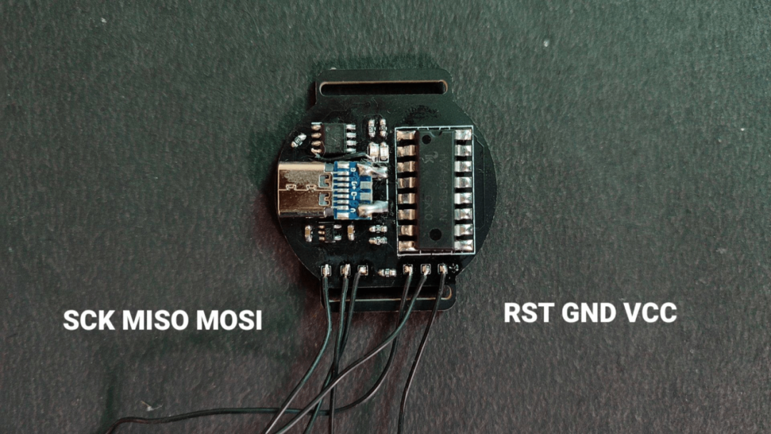
This connects the BCD watch PCB and Arduino as ISP pins. If you don’t know about using Arduino as ISP, you can watch this video:
To set the fuse bits, first download the folder from the GitHub page:
GitHub: <span>https://github.com/vishalsoniindia/BCD-Watch</span>
Open the folder, go into the <span>fuse</span> folder, and click the top bar in the <span>fuse</span> folder, as shown, type <span>cmd</span> to open the command terminal.
Open the <span>cmd.txt</span> file and copy the first line, then paste it into the command terminal. If you see “fuse OK”, it means it was successful.
Copy the second line from the <span>cmd.txt</span> file, paste it into the command terminal, and you will see “fuse OK” again, which means your controller is now set to <span>1Mhz</span>.
Step 8: Uploading Code
In the same folder, you will find the <span>Attiny85_link.txt</span> file. Copy the link provided in the file or copy it from below.
https://raw.githubusercontent.com/damellis/attiny/ide-1.6.x-boards-manager/package_damellis_attiny_index.json
Open the Arduino IDE, go to File, then Preferences, and paste the link into the additional board manager URLs section, separating it with commas “,” from other links.
Go to Tools -> Board Manager, and install ATtiny85.
Open the code, go to Tools, and select the board and processor as ATtiny85. The clock should be set to 1Mhz, and connect to the Arduino’s COM port as ISP.
Go to the code page and click upload using programmer.
After uploading the code, the watch will display an error value. Disconnect the ISP, connect it to an external power source, and press the button, then everything will work normally.
Step 9: Connecting the Battery
Here, we connect a 500mAh battery to the input capacitor of the LDO, as shown.
The red light indicates that it is charging.
After verification, we can secure the battery with glue. Although this is not a stable solution for now, it is effective, and we can consider using epoxy resin for a more permanent fix in the future.
Step 10: Watch Strap
You can find a pair of watch straps to install!
Original link: https://www.instructables.com/BCD-Watch-Binary-to-Decimal/
Original project author: vishalsoniindia
Translation first published by: DF Maker Community
Hardware Arsenal
Click to learn more👆
If you have any comments or corrections regarding the article translation, feel free to leave a message below!
If you cannot download the code involved in the project from the author’s GitHub repository, you can click “Read the original text” to download from the community forum!
Watch Series Review
▼ Open-source DIY ink screen watch! Stylish and practical, with wireless Bluetooth pedometer alarm clock!

Click to read👆
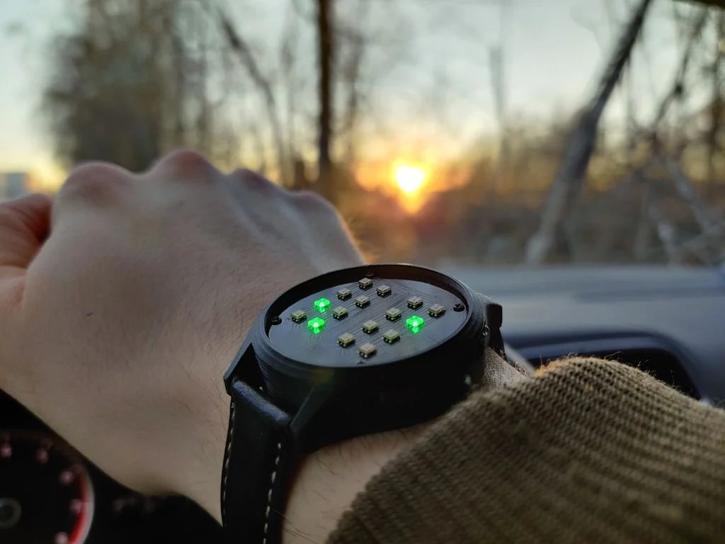
▼ Make an IoT watch with 200 LEDs using ESP32
Click to read👆
▼ IO Watch: Programmable watch made with Arduino UNO
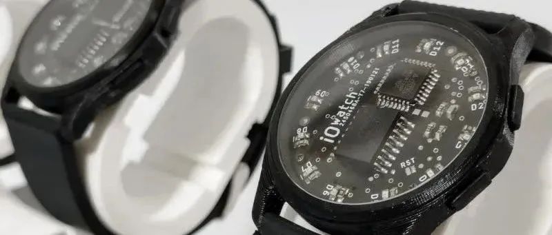
Click to read👆
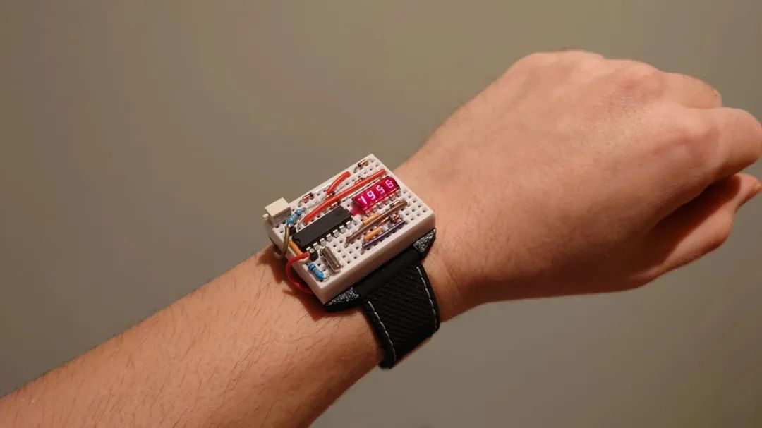
▼ DIY a practical and stylish binary watch
Click to read👆
▼ Replica Casio F-91W! But mine is bigger.
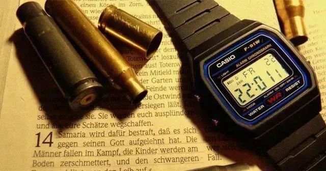
Click to read👆
▼ “Made a new watch for myself this New Year!”
Click to read👆
▼ E-ink screen watch – a project that is still unfinished
Click to read👆
▼ Paying tribute to Zhi Hui Jun? DIY a transparent astronaut-themed watch!
Click to read👆