▼ Follow our public account: Engineer Looks at the Sea ▼ Hello everyone, I am Engineer Looks at the Sea. Some friends have reported a few calculation errors in this article, and in the spirit of rigor, I am correcting them as follows (the parts in red text).
The battery charging and discharging circuit is one of the most critical circuits in a mobile phone, as it is the source of all the phone’s functions. If this circuit has issues, it can cause the entire phone to operate unstably or even fail to power on. The power for the phone comes from the battery, and the battery voltage is output to various loads after passing through the Power Management IC (PMIC). As shown in the figure below, the battery’s power is converted into a power called ‘system’ after passing through the PMIC, which serves as the main power supply for the phone. This power supply is referred to as Vsys on some platforms and VPH_PWR on others. In any case, everything is interconnected; regardless of what it is called, the power for other modules in the phone is derived from this power conversion. High-end phones have hundreds of power sources, while low-end phones have around sixty to seventy power sources, all coming from Vsys.
In very rare cases, if Vsys cannot provide the required high current load, one can consider drawing power directly from the battery Vbat, but this is an extremely uncommon application and design scenario.
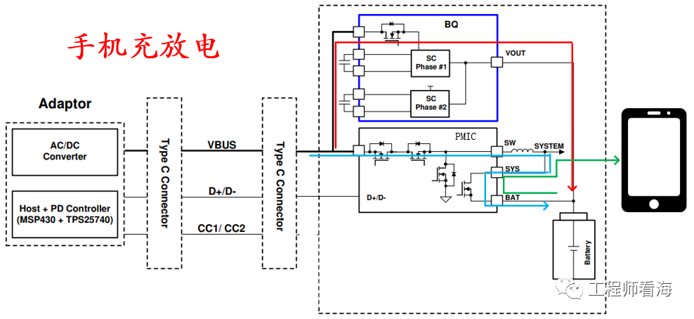
From the battery’s perspective, it discharges to provide energy for the entire phone and is also charged to store energy. During discharge, the current follows the output path, as seen in the green curve in the figure above, while during charging, it follows the input path, as seen in the light blue and red paths. The charging current from the USB charging cable enters through the Type-C connector and passes through the PMIC or auxiliary charging IC to reach the battery, enabling the charging function. In the charging path, the red part represents high-power charging via a charge pump, while the light blue path represents low-power charging via a BUCK converter. In fact, if we were to switch the light blue path, it would represent a BOOST structure, allowing the phone to also boost voltage and supply power to other devices through the Type-C interface.
Some students may wonder why charging requires two paths.
These two charging paths consist of a main charging path and an auxiliary charging path. The auxiliary charging path has a higher charging power, and the fast charging in our current phones mainly relies on the auxiliary charging IC to achieve high-power charging.
By combining the charging voltage and current curves shown in the figure below, we can gain a deeper understanding of the mobile phone charging process. If the battery is over-discharged or has not been used for a long time, resulting in a very low charge, even below 3.5V, the battery starts charging from 3V, which is called pre-charge. During the pre-charge process, the main charging IC is active, and the charging path follows the light blue curve in the figure above. The current in the USB cable is essentially the same as the current entering the battery. After pre-charging, it reaches the T1 CC stage (the CC stage is the Constant Current stage), characterized by a slow increase in battery voltage while the current remains constant. The current stabilizes at 3A, while the battery voltage gradually rises from 3V to 3.5V, slowly increasing the battery charge.
Next, from time T2 to T3, it remains in the CC stage. Starting from T2, the auxiliary charging IC begins to intervene in the charging process, as indicated by the red curve in the figure above. At this point, the charging power changes significantly; the current on the USB charging cable can reach 4A, while the current entering the phone is double the USB current, approximately 8A. The auxiliary charging IC in the figure is a buck charge pump charging architecture, characterized by halving the voltage and doubling the current. If the USB provides about 8V, and the battery voltage is 4V, this results in halved voltage and doubled current, where 8V * 4A = 32W. At this point, the charging power of the charger is approximately 32W. It is worth mentioning that the principle of the charge pump is referenced in a previous article: “Understanding Charge Pump Power Supply Principles in One Article”.
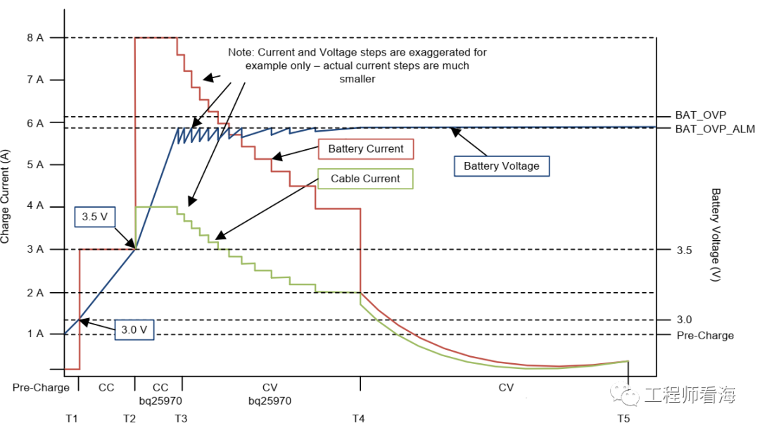
The duration of fast charging is very short. Once the battery reaches a certain level, the charging current will decrease, and the charging process enters the T3-T4 phase. At this point, the battery voltage remains unchanged while the current gradually decreases, which is called the CV process, or Constant Voltage charging. However, the USB current and battery current still maintain a 1:2 relationship, and the charging power remains significant.
After time T4, the charging power significantly decreases, the auxiliary charging IC rests, and the main charging IC gradually takes over. At this point, it enters the CV stage, and the battery slowly becomes fully charged.
This concludes the introduction to the mobile phone charging and discharging architecture and workflow. It is important to note that the battery’s charge and voltage are not 100% positively correlated. In less demanding situations, we can roughly estimate the charge based on battery voltage, but in mobile phones, where accuracy is crucial, a high-precision, user-friendly battery gauge design is essential. Therefore, it is necessary to estimate and fit the charge using both voltage and current. For example, some battery gauges use Kalman filtering to estimate the charge, while a simpler approach is to integrate the current and use it in conjunction with voltage to estimate the charge. Additionally, when the battery is low, the discharge can be particularly rapid, which can lead to an unfriendly user experience where a user sees 15% battery one second and suddenly 1% the next. In some cases, playing a game can even cause the battery percentage to spike, which is also a very unfriendly experience.
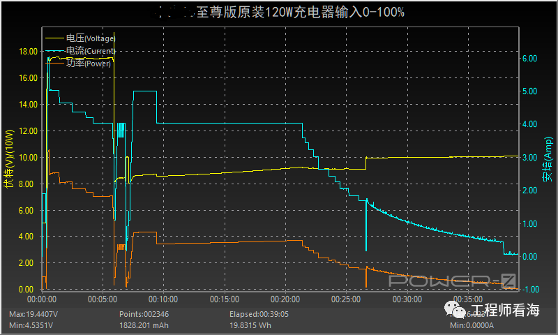
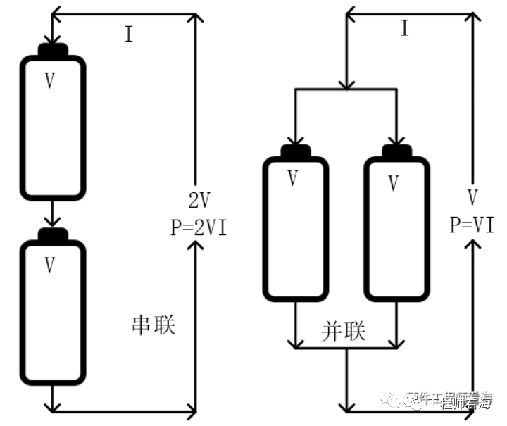
Let’s take a look at the actual charging curve. The figure above shows the measured charging curve of a certain mobile phone, where yellow represents USB voltage, blue represents USB current, and orange represents power. The duration of high power is only a short segment. This phone uses a more complex battery and charging architecture design: 120W fast charging technology, which employs two charge pump designs to convert the high voltage and current of the USB network (20V 6A) into two paths of 10V 6A voltage and current, ultimately merging into a 10V 12A high current input to the battery, achieving 120W fast charging. To realize 10V 12A battery charging, this phone uses a dual-series battery architecture. The characteristics of dual-series batteries are: total voltage increases, capacity remains unchanged; while dual-parallel batteries have the characteristics of: total voltage remains unchanged, capacity increases. Due to the series connection of the batteries, the total voltage doubles, which, under the same total current, results in faster charging power due to the series design.
This concludes the introduction to the mobile phone charging and discharging architecture and workflow. However, what I hope for even more is the advancement of battery technology itself, with larger capacity, greater stability, and faster charging batteries being the fundamental goal.
If you have read this far, please like, bookmark, and share!
Limited-time free QR code to join the group for more industry technology discussions

Recommended Reading▼
Battery, Power
Selected Hardware Articles
Huawei HiSilicon Software and Hardware Development Materials