With the development of computer technology, railway interlocking has been upgraded, leading to the emergence of computer interlocking. The difference between computer interlocking devices and the 6502 electrical interlocking is the addition of a driver acquisition circuit, which delegates the interlocking computation tasks to the computer.
Regarding the driver circuit, the figure shows the station signal machine driver acquisition circuit. Different computer interlocking systems have different driver and acquisition circuits; for example, the Casco ILOCK computer interlocking features dual drive and dual acquisition, while the JD-1A computer interlocking uses the JPCX-1000 relay for driving. Although the driving methods differ, they are generally similar.
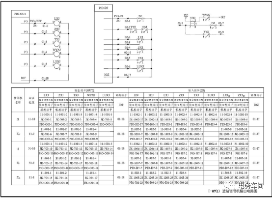
The driver board converts the data from the interlocking machine into relay output signals, which are sent to the combination side through the interface frame, and then enter the combination to drive the relay to attract. The driving methods include: positive voltage output with shared negative voltage; both positive and negative voltages are output by the computer interlocking. Taking the station signal machine interface circuit as an example, when troubleshooting the driver fault of the computer interlocking device, if the main line is connected to the train, the single yellow light LXJ↑, ZXJ↑, TXJ↓ will light up.
If LXJ cannot attract, the signal machine will display a constant red light. After the relay is driven, the driver board will show a green light on the electrical maintenance machine. After confirming that the relay failure to attract is not caused by interlocking condition computation, use a multimeter in the DC 50V range to test if there is DC 24V at 01-17 and 01-18, and use IOZ (01-17) to test if the relay coil has voltage. The point where voltage changes from present to absent indicates an open circuit; if there is no IOZ in the combination, it can be borrowed from another combination or use IOF for troubleshooting (not recommended due to the risk of misjudgment). When the signal is not open, there will be no voltage in the circuit, and resistance measurement can be performed. When measuring resistance, different values may be obtained by switching the probes. One side tests the internal resistance of the board circuit, while the other tests the resistance of the relay coil (resistance values such as 1700 or 1000Ω, etc., vary according to the relay model).
If ZXJ cannot attract, the signal machine will first show a double yellow light, then a red light (when the single yellow light is lit for 2DJ, it should not be able to collect 2DJ. The figure shows an error in the 2DJ acquisition circuit). Such normally attracting relays can be tested for faults using power, and the resistance method cannot be used.
When troubleshooting with both positive and negative power supplied by the computer interlocking, it is important to pay attention to the power polarity. The author found that during the use of a certain training device at school, the driver acquisition board had a small voltage output under normal conditions (depending on the internal circuit of the board), which can be utilized to troubleshoot faults. (This method is merely a conjecture, and readers are encouraged to practice it themselves). If the interface frame is disconnected, be careful to identify the terminal functions to avoid checking the wrong terminal.
The acquisition circuit also has various acquisition methods, such as unipolar acquisition and multipolar multi-channel acquisition, as shown in the figure for unipolar acquisition. Signal machine acquisition faults manifest as the actual lights of the signal machine being lit, and if the acquisition fails, it delays the signal machine to change to red to avoid signal upgrades. In troubleshooting acquisition faults, power can also be borrowed, or grounding methods can be used (as there is usually power in the circuit, the resistance method cannot be used).
The short-circuit fault of the acquisition drive can cause protection of the driver board, which can be checked by disconnecting wires.
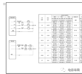
The switch acquisition driver circuit is shown in the above figure. When operating the switch, both YCJ and DCJ must attract simultaneously for the switch to operate. If YCJ does not attract, it should first be determined whether the interlocking conditions for YCJ to attract are met (the opposing route has not been established, the switch is not single-locked, and the total lock in the throat area where the switch is located has not been pressed). When troubleshooting drive faults, similar methods to signal machine drive faults can be employed, using resistance and voltage methods (borrowing IOZ or IOF).
Switch acquisition faults should be particularly noted; as shown in the figure, if there is a poor connection between the YCJ11 contact and the side 01-17, it will cause both the normal and reverse positions to indicate no signal. If the switch operates normally and the normal and reverse position indicators show both AC and DC voltages and the relay is normal, it indicates an acquisition fault. IOF or IOZ can be borrowed for troubleshooting.
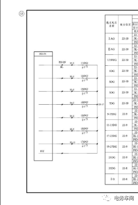
The track circuit acquisition circuit fault mainly manifests when DGJ attracts, yet the control console still shows a red light. The troubleshooting method also uses the voltage method because DGJ’s normal attraction makes it relatively easy to check, so no further elaboration is provided.
Conclusion: Reasonably borrowing the electrical maintenance machine to assist in judgment can save a lot of time when dealing with acquisition drive faults. It is not recommended to use the same polarity power to troubleshoot because poor contact between probes and terminals can lead to misjudgment. (When no voltage is detected, first shake the probes to avoid misjudgment due to poor contact). The grounding method also requires summarization through practice, and I hope everyone can develop a method that suits themselves. This article represents personal views, and any inaccuracies are welcome for correction.
6502 is divided into selection group circuits and execution group circuits, equivalent to the acquisition and driving of computer interlocking.