In daily work, many people often ask about the difference between CDR solutions and DSP solutions, especially in the context of QSFP56 200G SR4 and QSFP-DD 400G SR8 optical modules and their corresponding AOC series products. This article will detail the differences in functionality, principles, technical characteristics, application scenarios, and implementation methods of the two solutions.
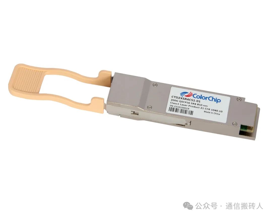
In optical modules, CDR (Clock Data Recovery) solutions and DSP (Digital Signal Processing) solutions are two different signal processing technologies primarily used to address signal recovery and noise suppression issues in high-speed optical signal transmission. Below are their core differences:
1. Core Functions and Principles
CDR Solution:
– Function: Extract synchronous clock from the received distorted signal and realign the data.
– Principle: Based on phase detection (such as Pilot Tone, Phase-Locked Loop (PLL)) or data-aided algorithms, it recovers the clock through analog circuits or simple digital logic.
– Point of Action: Typically located at the front end of the optical receiver (electrical domain), immediately after the optical detector.
DSP Solution:
– Function: Performs comprehensive digital processing of the signal through algorithms, including equalization, filtering, and Forward Error Correction (FEC).
– Principle: Utilizes digital signal processing techniques such as Discrete Fourier Transform (DFT) and Finite Impulse Response (FIR) filters to compensate for channel loss and dispersion.
– Point of Action: Typically located at the digital backend of the receiving link, which may require more complex computing units (such as ASIC/FPGA).
2. Comparison of Technical Characteristics
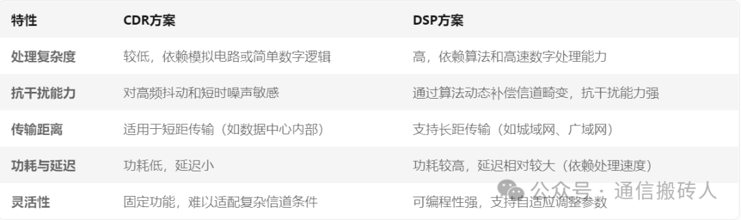
3. Typical Application Scenarios
CDR Solution:
– Short-distance high-speed optical modules (such as 200G QSFP56 within data centers).
– Cost-sensitive scenarios with relatively lower signal quality requirements.
– Systems requiring low power consumption and high real-time performance.
DSP Solution:
– Long-distance transmission (such as inter-data center interconnections, optical fiber backbone networks).
– High channel density scenarios (such as CFP8-ZR, OSFP packages).
– Needs to address complex channel effects (such as dispersion, non-linearity, multi-mode interference).
4. Differences in Implementation Methods
CDR Implementation:
– Common Technologies: Phase-locked analog PLL circuits or low-order digital CDR (such as DDC).
– Example Chips: Receiver ICs with integrated CDR (such as Marvell’s SerDes chips).
DSP Implementation:
– Common Technologies: Discrete-time filters, equalization algorithms (such as Linear Equalization (LE), Decision Feedback Equalization (DFE)), Forward Error Correction (FEC).
– Example Chips: Programmable FPGAs or dedicated ASICs supporting DSP (such as InfiniBand’s DSP engines).
5. Cost and Performance Trade-offs
CDR Solution:
Advantages: Low cost, low power consumption, simple circuitry.
Disadvantages: Performance is limited at high rates (e.g., may struggle above 200G).
DSP Solution:
Advantages: Supports flexible tuning and high performance, adapts to complex channels.
Disadvantages: High hardware costs, complex algorithm development, higher power consumption.
Conclusion
CDR is a fundamental signal recovery technology suitable for short-distance, low-cost scenarios;
DSP is a more advanced digital processing solution that compensates for physical layer defects through algorithms, suitable for long-distance, high-speed, and high-capacity requirements.