Currently, PLCs are widely used centralized control devices in industrial production and automation control, replacing cumbersome relay cabinets, AC contactor cabinets, etc., and are gradually being popularized in production and control. Correct wiring of the PLC is a prerequisite for its functionality, and mastering the wiring of PLC input and output terminals is essential for every electrical operator.
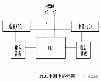
Generally, the PLC power input terminal is connected to AC220V to provide operational power for the PLC. The PLC output power terminal is usually DC24V, which is the built-in power output of the PLC. Correct wiring of the input and output terminals during PLC use is very important; proper wiring is the premise for the PLC to work.
Let’s focus on analyzing the common wiring types for PLC input and output terminals:
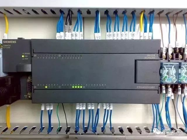
1. Common Wiring Types and Objects for Input Terminals
PLC input terminals generally receive:
1. Digital signals: buttons, limit switches, toggle switches, proximity switches, dip switches, etc. A simple example makes this clearer:
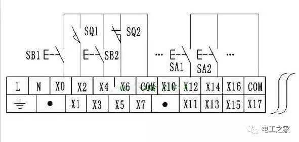
Wiring diagram for PLC and button switch
The wiring of the button or proximity switch is shown: PLC digital signal wiring, one end connects to the PLC input terminal (X0, X1, X2, etc.), and the other end connects together to the PLC common terminal (COM terminal).
2. Analog signals: generally various types of sensors, such as pressure transmitters, level transmitters, remote pressure gauges, thermocouples, and thermal resistors, etc. The wiring method may vary slightly depending on the type of analog signal acquisition equipment (two-wire or three-wire systems). As shown in the figure:
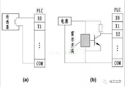
Interface circuit between PLC and sensor components
(a) Two-wire sensor; (b) Three-wire sensor
2. Wiring for Output Terminals.PLC output terminal wiring can generally be divided into three situations: 1. Relay output. 2. Transistor output. 3. Thyristor output.
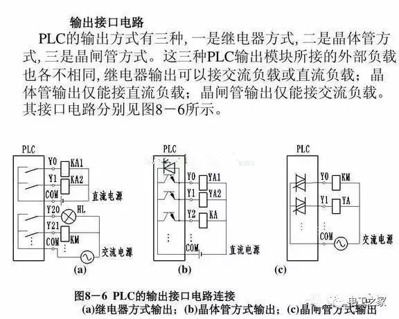
Different PLC output methods require different types of power for the output load. As shown in the figure: this is the basic wiring for PLC input and output terminals, which is basic knowledge of PLC.
3. Three Points of Knowledge in the PLC Wiring Process:
1. PLC Power Circuit.
The power supply for the PLC control system includes not only AC power but also the PLC’s DC power. Generally, the PLC’s AC power can be supplied directly from the mains, while the DC power for input devices (switches, sensors, etc.) and output devices (relays) is best supplied by independent DC power sources. Most PLCs come with a 24V DC power supply, but this should only be used when the input or output devices do not require a large current.
2. Current Ratings for PLC Input and Output Ports.
The built-in input power for PLCs is generally DC24V, with a current rating between 5mA-7mA per input point. This current is the maximum current produced when the input port is shorted. When there is a load on the input port, the current flowing through it will be correspondingly reduced. The minimum current required for effective input signal transmission is generally 2mA, so the total impedance of the devices connected to the input port should generally be less than 2K ohms.
Interface circuit between PLC and sensor components
(a) Two-wire sensor; (b) Three-wire sensor
This means that when the sensor power at the input port is relatively high, an external power supply is required.
3. The maximum current that PLC output ports can generally pass varies with the PLC model, mostly between 1A and 2A. When the load current exceeds the maximum rated current of the PLC port, it is usually necessary to add an intermediate relay to connect external contactors or other devices.
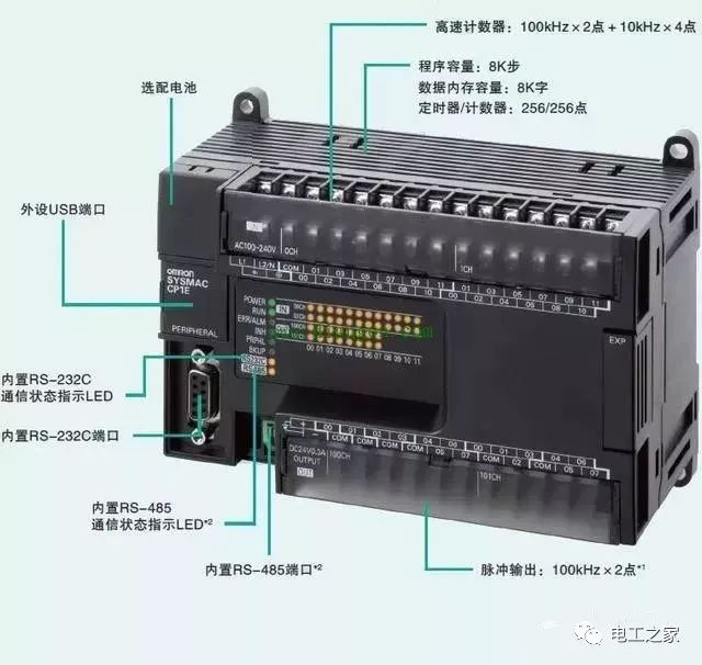
Correct wiring of PLCs is a prerequisite for their effective operation and is a fundamental skill of PLCs. Mastering the common knowledge of PLC wiring is very necessary.
Source: Electrical Engineering Home
Business Cooperation: 010—88379790 ext. 802, 822
Disclaimer: This article is a network reprint, and the copyright belongs to the original author. However, due to numerous reprints, the true original author cannot be confirmed, so only the source of reprint is indicated. If there are copyright issues with the videos, images, or texts used in this article, please inform us as soon as possible, and we will confirm the copyright based on the proof materials you provide and pay remuneration according to national standards or immediately delete the content! The content of this article represents the author’s views and does not represent the views of this public account or guarantee its authenticity.